Definition of Main View
Within ProSteel, there are different variants to specify the main view (front view) of a shape for detailing.
Experience showed us that in most of the cases it isn’t enough to assume a firm guideline here because this specification is individually made by the executive design engineer and mostly also depends on the constructive environment. As it is a matter of component parts in the space, you cannot clearly define top/bottom or left/right.
Front View based on the Part Coordinate System (A)
Since each component part has its own coordinate system, a clear and constant main view can be specified with the help of this coordinate system. In case of standard shapes, the Y-axis of this coordinate system is always aligned parallel towards the web so that it can serve as reference axis for the plan view. The Z-axis normally runs in longitudinal direction of the shape.
The direction of the X-axis determines the front view to guarantee that the plan view is always from the top to the web and that in case of non-symmetrical shapes (e.g. U- and L-shapes) in front view you can always look inside the shape. This is defined in this way for all shapes without any exception in favour of a uniform guideline from the 3D model.

the part coordinate system of an L-shape (X, Y, Z) with the starting point S and the endpoint E of insertion direction
For detailing the front view, the coordinate system now is rotated in the way as shown by the new axes (X', Y’, Z’ and S' resp. E').
Front View based on the Global Front View (B)
To avoid exchanging up and down you can determine two global front views. The view in the direction of the "nearest" part coordinate axis is assumed as front view of the corresponding shape. To avoid the view on a cross-section you can define an alternative front view, which mostly has been rotated by 90°.
You obtain the result that the position is always independent of the insertion direction of the part (base plates are always "at the bottom"), but the front view once can show the web and once the flange – depending on the rotation of the shape in the view. Tough, parts that are situated further back in construction are displayed as seen from inside.
Select the entry Set Global Reference View in the context menu of the component parts list to specify the global front views. Then, you have to click into the model to get the cross hairs for selection. After that, you select the desired view direction of the front view and then the alternative view direction.
When you press the <Esc> key instead of selection the views are reset to the default values (0,-1,0) and (1,0,0). The current values are displayed in the information window.
Front View based on the Outside of the Model (C)
This variant is similar to the global front view. The difference is that instead of specified reference views you always choose the part coordinate axis, which show most clearly from the center of construction to the outside. This means that the front view is always what you would see from the outside if you looked towards the center of the whole construction.
This method largely corresponds to human imagination, but depending on the rotation of the shape, once the web and once the flange can be displayed.
The following example shows the effects of the selected main view on the 2D-display of a shape:
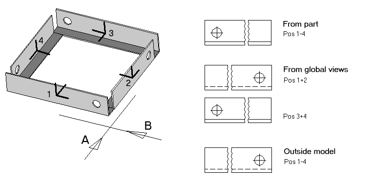
Positions 1-4 have been inserted at a rectangular, the Y-axis of the part is showing to the top and the Z-axis is showing in shape direction. The views A and B are the specified global front views.
Depending on selection, you will get the front view displayed on the right.
Specify Individual Front View (D)
The last variant is that you can specify for each individual part separately which part coordinate axis has to serve as front view. In general, you can decide to use variant (B) or (C) and align unfavourable parts individually and independently.
Select the entry Set Individual Reference View in the context menu of the component part list to specify an individual front view. Then, you have to select the desired part to get the cross-hairs for selection. After that, you choose the desired view direction of the front view.
When you press the <Esc> key instead of selection the individual front view of the part is deleted. The current value is displayed in the information window. Select the entry Reset All Reference Views in the context menu of the component parts list to delete the specifications for all component parts simultaneously.