| Layout of Plate
|
Sets the connecting plate layout, can override the
default layout set when invoked by the tool.
- Automatic - The
application determines which layout type to be used depending on the position
of the selected shapes.
- Splice -
Creates an end splice connection between two members. Enables the
Rotation setting, additionally.
Note: The
threshold angle, which differentiates between, spliced and standard plate
connections is approximately 45°. If you want to create the
Flange type, you need to set it
explicitly as otherwise a plate connection at the web is always created.
Tip: You can define a separation line
for a continuous shape by pressing <Enter> or by right-clicking the
mouse when you are prompted for the supporting shape.
- Flange -
Creates a connection between a beam and the flanges of a supporting member.
This option must be selected manually. It is not automatically selected by the
application (using the
Automatic option).
- Normal -
Creates an end plate connection between the member and either the web or flange
of the supporting member.
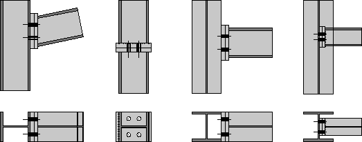
Different
connection types which can be created. From left to right: Normal (automatic),
Splice, Flange, Normal (automatic)
The Normal layout is usually best
suited, e.g. for connecting rafters by endplates at a fixed midline. The End
Plates connection keeps the member dimensions intact, that can be ensured by
preferably keeping the ECS axis turned on.
|
| Plate Dimensions
|
|
| As Polyplate
|
When checked, the inserted end plates are not
created as polyplate objects, instead of as flat steel.
|
| Rotate Connection
|
When checked, turns the complete connection by 180°
around the insertion axis, if upper and lower side were exchanged at generation
of the connection. In case of asymmetric plates you can define the plate
position here.
|
| Plates Equal
|
Enabled when
Doubler Plate is checked. Sets all the
dimensions of the doubler plate equal to those of the main end plate.
|
| Rotate Flat Steel
|
Enabled when
As Polyplate is unchecked. Rotates the
inserted flat steel endplate by 90°. This affects change in the dimensions.
|
 (Retrieve plate dimension from a
shape) (Retrieve plate dimension from a
shape)
|
Adjusts the first plate to the cross-section of any
existing shape selected in drawing.
|
 (Copy dimension of 1st plate to
2nd) (Copy dimension of 1st plate to
2nd)
|
Copies the data of the first plate into the input
fields of the second plate.
|
| Gap
|
Sets a space between the supporting shape and the
plate. This allows you to consider finishing tolerances.
|
| Plate Offset
|
- Hoizontal –
Sets the horizontal connection offset distance. Shifts the entire endplate
connection parallel to the flange of the connecting shape by the offset value.
- Vertical – Sets
the vertical connection offset distance. Shifts the entire endplate connection
parallel to the web of the connecting shape by the offset value.
|
