| Joist Plate
|
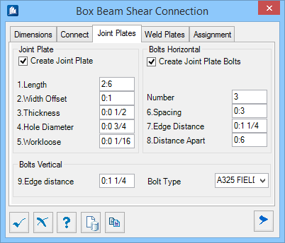
- Create
Joist Plate – When checked, creates joist plates.
- Length – Sets
the length of the joint plate. A positive value determines the length . A
negative value is read as its absolute value. The default is 800 or 32
depending on the units setting.
- Width
Offset – Sets the offset of the plate to the edge of the Connection
shape in the direction of X-Axis of the Connection shape. The default is 20 or
0.8 depending on the units setting.
- Thickness –
Sets the plate thickness. A positive value determines the thickness. A negative
value is read as its absolute value. The default is 15 or 0.6 depending on the
units setting.
- Hole
Diameter – Sets the dimension of the holes. A positive value
determines the diameter. A negative value is to be read as its absolute value.
The default is 16 or 0.6 depending on the units setting.
- Workloose –
Sets the workloose of the holes. A positive value determines the workloose . A
negative value is to be read as its absolute value. The default is 1 or 0.04
depending on the units setting.
|
| Bolts Horizontal
|
Defines the number and distance of the bolts on the
flanges of the Support and Connect shapes along the direction of Connection
shape.
- Number – Sets
the number of the bolts in the direction of Connection shape. Default is 3.
- Spacing – Sets
the distance between two adjacent holes along the direction of Connection
shape(refer to the picture above). Default is 60 or 2.4 depending of the units
setting.
- Edge
Distance – Sets the offset of the center of the holes to the edge
of the plate along the direction of the Connection shape(refer to the picture
above). Default is 30 or 1.2 depending of the units setting.
- Distance
Apart – Sets the distance between the hole center in the Support
shape and center of the first hole in the Connection shape along the direction
of Connect shape(refer to the picture above). Default is 180 or 7 depending of
the units setting.
|
| Bolts Vertical
|
Defines the number and distance of the holes on the
flange of the Support and Connection shapes along the X-Axis of the Connection
shape.
- Edge
Distance – Sets the distance between the end edge of the joint
plate and the center of the first hole along the X-Axis of the Connection
shape(refer to the picture above). Default is 30 or 1.2 depending of the units
setting.
- Bolt
Type – Sets the type of the bolt being created. The default is
DIN 7990.
|