Chamfer Between Elements
 Used to plane a corner, example, it alters an existing intersection by inserting a line between the elements.
You can access this tool from the following:

-
Open the Civil Tools task pane to the Horizontal Geometry section then click the Chamfer between Elements icon.
-
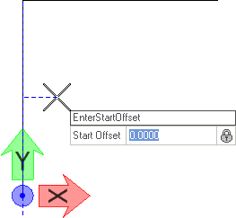
When you move the cursor into the View, it is equipped with a command prompt requesting that you "Locate First Element", so move the cursor to the element from which you wish to chamfer then data point ( i.e., left-click) on it.
-
Use one of the following methods to set the Start Offset:
-
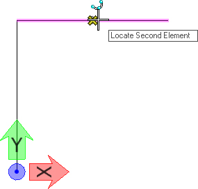
The prompt says, "Locate Second Element", so move the cursor to the element to which the chamfer must extend then data point.
-
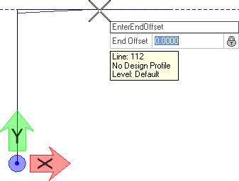
Use one of the following methods to Enter End Offset:
-
Move the cursor into the space between the two elements. The prompt says, "Define Approach Length", so use a combination of the following methods to define the approach leg of the chamfer (navigate the options by striking the left or right arrow keys):
-
Enter a value for Approach Length then strike the Enter key.
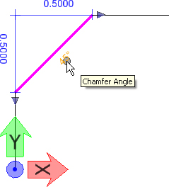
-
Enter a value for Chamfer Angle then strike the Enter key.
After entering the values that define the transition, data point to execute the command.
-
- The prompt says, "Define Radius", so use a combination of the following methods to define the exit leg of the chamfer (navigate the options by striking the left or right arrow keys):
-
Enter a value for Back Radius then strike the Enter key.
-
Enter a value for Ahead Radius Parameter then strike the Enter key.
Note: By adding back and/or ahead radii, allows you to construct a curve-line-curve construction instead of a simple line.After entering the values that define the chamfer, data point to execute the command.
-
- To trim the element(s) at the intersection of the chamfer or to extend the chamfer to intersect with the existing elements, your Offest value must be zero. Strike the down arrow key to choose from the available options then strike the Enter key.


Manipulators
Manipulators are available for:
-
Move
-
Length
-
Chamfer Angle
-
Curve Radii when back and/or ahead curves are included in the construction
Properties
To View the new element's properties, equip the Element Selection tool.

Data point on a chamfer in the View then let the cursor hover over the selected element. Click the Properties icon to access rule data for the chosen element.