Workframes
All OpenBridge Modeler models are started with the creation of one or several Workframes. A Workframe represents the basic spatial dimensions of your project in a 3D view.
Workframes aid 3D orientation because they can display the basic system dimensions (for instance, axes dimensions) as design aid objects, which automatically create the associated ACS systems of the views created by defining the workframe.
At minimum, the workframe includes the grid and guide lines you use to help place model components. Based on the project and your own personal options, you can:
- Use the Workframe dialog to automatically add elements — such as columns, beams, floors, walls, footing pads, and footings.
- Place the basic workframe, and then use OpenBridge Modeler's many powerful tools to manually add elements.
However you choose to add elements to your model, you have complete control over dimensions for each item. OpenBridge Modeler also provides you the flexibility to edit or delete individual elements even after you complete your workframe.
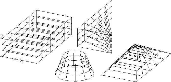
Basic Workframe Types
Before defining a workframe, first decide basic shape desired. The following choices are available:
- Rectangular workframes
- Cylindrical (also conical) workframes
- Wedge-shaped workframes
- Pyramidal workframes
Workframes Are Objects
One of the great strengths of OpenBridge Modeler is its object-orientation; and workframes are good examples of this.
This means that previously created work frames can be modified and manipulated using standard commands. You can move, rotate, etc. the work frame or even just partial views - the displayed work planes - and the correct ACS settings.
If a view is selected, you see the expected view. The associated ACS system adjusts itself to the movement of the object.
You can subsequently set up individual cutting planes for each work plane and make other modifications by selecting the workframe, right-clicking, and selecting Change Structural Properties from the pop-up menu.
The platform is moved and the entire work frame 'hangar' and 'platform' is rotated.
The platform is moved and the entire work frame 'hangar' and 'platform' is rotated.
Click on the 3D-grid via Change Properties, and the divisions or even the basic shape of the frame can be modified..

Multiple Workframes Within a Single Model
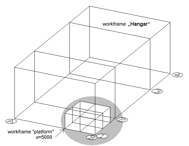
You can define as many different work frames within one model as desired. They are then distinguished from each other by their group names.
This group name is a prefix preceding the view name. For instance, hangar_TOP and platform_TOP (with "hangar" and "platform" being the group names specified by you).
This makes it possible to set and specify all-important areas of the project even before the 3D model is built and accesses them easily.
A platform with the dimensions 3000 x 3000 and the height 1500 is to be inserted as displayed.
The coordinates of the origin are set to y=0, x=5000, z=0 and the group name is platform – the other settings match the size and sections.
When selecting the views to be created, the overlapping views of the same work plane of other workframes may be omitted because normally they are of no further use for you (when selecting the corresponding plane, you will see the whole view).
In connection with the object-oriented feature of OpenBridge Modeler there are good reasons for creating these views. It is, for example, possible to move the complete work frame and this view is perhaps missing. However, if the above picture corresponds to the reality, you can omit the front and right side view of the platform because the "hangar" work frame already provides them.