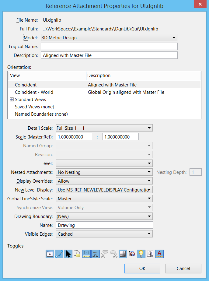
Reference Attachment Properties Dialog
| Setting | Description |
|---|---|
| File Name | Shows the reference's name. |
| Full Path | Shows the full file specification for the reference, including the directory. |
| Model | Lists the models within the reference. Used to select the model to be attached to the master model. |
| Logical Name | Sets the logical name of the model.
Since the same model can be attached many times, the logical name helps you distinguish between references. |
| Description | Sets the optional description for the model. By default, this is the same as the models description in the Models dialog. |
| Orientation | Sets the view of the model being attached. The list
may also include saved views and named boundaries. You can select multiples of
a type of orientation to attach. For example, you could attach multiple saved
views. Coincident and Coincident World are treated as the same type.
|
| Detail Scale | Represents the Master:Ref scale in terms of the
sheet scale. For example, if your sheet annotation scale is 1/8 = 1’ and you
want to place a detail reference of scale 1/4 = 1’, select the new scale from
the Detail Scale drop-down list. It automatically computes the Master:Ref scale
as 2:1.
When attaching a reference (a design or drawing model) into a sheet model, the referenced model's annotation scale is applied as the default detail scale, and the reference scale (Master:Ref Scale) is calculated from the detail scale and the sheet annotation scale. However, if the reference model’s annotation scale is Full Scale 1:1, the default detail scale is set to be same as the sheet annotation scale and the reference is attached at full size. |
| Scale (Master:Ref) | Sets the ratio of the master units in the active model to the master units in the attached model. |
| Named Group | Identifies a named group used to limit the elements displayed in the reference. |
| Revision | If Design History is on in the referenced model, lets you select the revision to the reference. If the original revision of the reference no longer exists you must reattach the reference. |
| Level | Sets the level for the reference to be attached.
For attached references created
prior to
MicroStation PowerDraft
V8i
(SELECTseries 1) — If View Display is off, or if Global Freeze or Viewport
Freeze is on for the level on which the reference is placed, elements in the
reference are not displayed.
For attached references created in MicroStation PowerDraft V8i (SELECTseries 1) or later — If View Display or Global Display is off, or if Global Freeze or Viewport Freeze is on for the level on which the reference is placed, elements in the reference are not displayed. For DWG attachments — If a level is frozen, references on that level are not displayed. For more information, see level display setting. |
| Nested Attachments | Determines how nested references (the references attached to the model selected as the reference) are handled for this reference attachment. See Nested Attachments list box in the Information Panel of the References dialog. |
| Nesting Depth | Sets the number of levels of nested references that
are displayed. Child references can have their own referenced models, which, in
turn, can have more referenced models, and so on. See
Nesting Depth in the Information Panel
section.
|
| Display Overrides | Controls how overrides are saved for nested
references. For each nested reference, overrides allow you to control the
settings for reference display, locate, snap, raster reference display, and
level display. See
Display Overrides list box in the
Information Panel section.
|
| New Level Display | Specifies whether a reference displays new levels.
See
New Level Display in the Information
Panel section.
|
| Global Line Style Scale | Controls the scaling of cosmetic custom line styles.
Every model can have a global line style scale factor that is applied to every
line style within the model. This factor is set in the
Properties dialog when the Line Style Scale is set to Global
Line Style Scale or Compound Scale. Alternatively, you can use the ACTIVE
LINESTYLESCALE key-in to set the global scale factor for custom line styles.
The specified scale factor has the same effect as the Scale Factor setting in
the Properties dialog. The Line Style Scale can also be set to follow the
Annotation Scale, in which case this value will be ignored, or it can be set to
Compound which will scale by both the Annotation scale and the Global Linestyle
Scale.
The scale of line styles within a reference can be affected by the global line style scale of either the active model, the referenced model, both, or neither.
|
| Synchronize View | When you attach a saved view, set this drop-down to
All Settings to synchronize with the original saved view. To attach the saved
view in unsynchronized state, set this drop-down to Volume Only, Presentation
Only, or None.
In order to change the appearance of a reference, you have to modify the saved view that it is synchronized with. This is to ensure fidelity of display properties such as view attributes, view display, clip volume, display styles and others. When synchronized, the reference location is also realigned. Specifically, when the reference is synchronized with the saved view, the reference center and saved view center remain aligned. You can see the effect of this in two ways:
In case of Volume Only, the clip volume and camera position is taken from the saved view. So if you change the original saved view, its clip volume as well as camera position will be changed. Also, the clipping is computed from the saved view boundary. Hence you cannot clip or mask the reference in Volume Only. The Presentation Only option is similar to Volume Only, except that in Presentation Only, you can modify the reference clip boundary. In the reference attachments that are created in versions prior to MicroStation PowerDraft V8i (SELECTseries 3), the unsynchronized references are listed as Clip Only. In this case, if you change the original saved view, only its clip volume will be changed and the camera setting will remain as it is. |
| Drawing Boundaries | (Available only when the active model is a sheet model) Shows the list of vacant drawing boundaries in the selected sheet. When attaching a reference on a sheet, you can optionally select an existing drawing boundary or create a new drawing boundary. A drawing boundary describes a drawing on a sheet. For example, if there are four references on a sheet (top, front, right, and isometric), you create four drawing boundaries to demarcate the four references. It plays a crucial role in automatically linking callouts across sheets. Properties such as Name, Detail Scale, and Identifier are displayed in the callouts in the form of fields. You can create a new drawing boundary by selecting New in the drop-down list. The list of drawing boundaries displayed in the drop-down list are filtered by the type of saved view selected in the Orientation section. |
| Name | (Available only when New is selected in the Drawing Boundaries drop-down list) Lets you enter a name for the new drawing boundary. |
| Visible Edges | Sets the visible edges display option. Options are:
This option is available only when a 3D model is attached directly to a 2D model. You can change the default selection of this drop-down list by defining the MS_REF_VISEDGE_ATTACH_STATE configuration variable. |
| Toggles | Defines settings for the reference.
The icons correspond to columns in the References list box and information panel. If an icon is pressed, the setting is on. Click the icons to toggle the settings on or off. |