MicroStation Help

To Create a Surface with Guide Wires

  1. Select the Loft Surface tool ( Modeling > Surfaces > Create Surfaces > Loft > Loft ).

  2. In the tool settings, click Loft by Sections with Guide Wires.

  3. Select a Guide Wire.

    A Guide Wire can be a curve or the edge of a surface or solid.

  4. (Optional) Press the <Ctrl> key to select a second Guide Wire.
  5. Select the first profile.
    Note:
    • While selecting the profile, ensure that the selection point is not on a node but rather can be anywhere on the segment between consecutive nodes.
      If you define incorrect start Point, then you will be alerted with Incorrect loft geometry in the message center.


      Error at the bottom


      Error in the Message Center

    • When selecting profiles for creating a loft feature, ensure that the "Direction of curve" is the same for all profiles.
      If the direction of curve is opposite, and you try to generate a Solid then you will be alerted with Loft operation failed in the message center.


      Error at the bottom


      Error in the Message Center

  6. Press the <Ctrl> key for additional profiles.
  7. To preview, enter a data point.
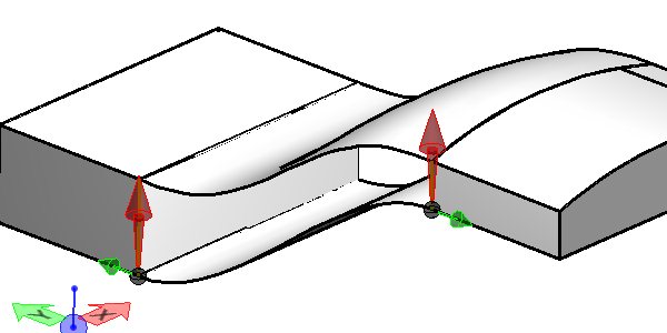
  8. Enter a data point to accept the surface or Reset to reject.


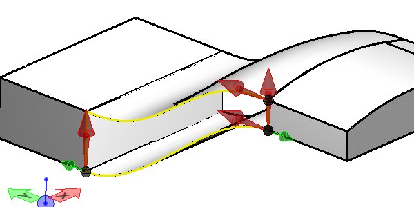
    The two red horizontal arrows are the Guide Wires and the two red vertical arrows are the profiles. Notice that the edges of the surfaces have been used as the Guide Wires and the edges of the solid have been used as the profiles. Profile and Guide Wires do not have to be part of a surface or a solid, they can be elements. The Profile ends must come in contact with the Guide wires. | The resulting surface is matched to the edges of the two surfaces.


    The Loft by sections without Guide Wires was used and the same edges of the solids were selected with Tangency for Start and Ending Continuity.


    The undesirable surface was created with gaps and overlaps.