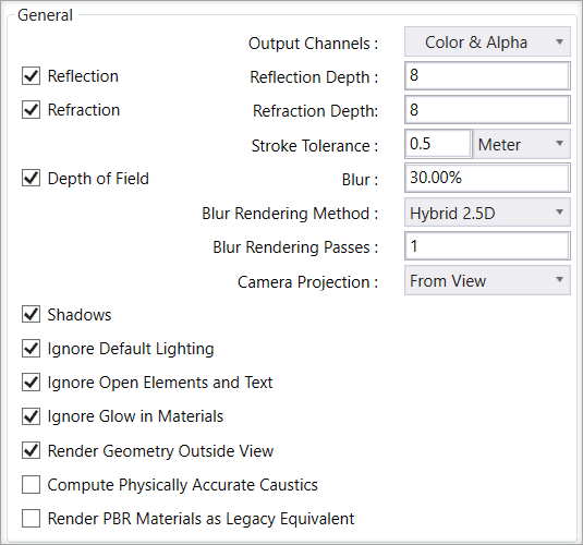
| Output Channels
|
Allows you to choose a rendering output. When
enabled, the render engine will render a separate channel for the selected
channels. When the render completes, you can use the save option from the
render dialog and the selected channels will be saved to files.
Note: Color &
Alpha will always be rendered while ray tracing and is always enabled for all
ray tracing render setups.
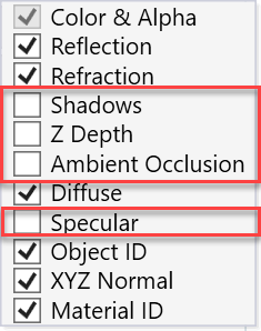
Channels marked in red in the below image are not supported
by Path Tracer:
|
| Reflection
|
Determines how the reflection rays are traced in a
raytraced render.
-
Reflection Depth - This setting
determines the number of times a reflection is seen. For example, imagine a
kaleidoscope that reveals geometric patterns using a set of mirrors.
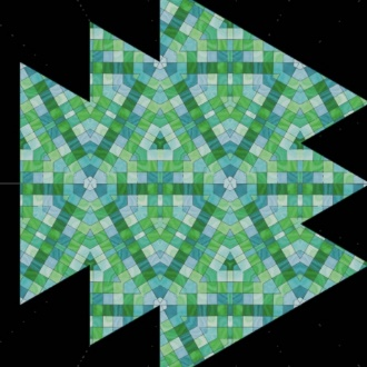
Top:
Reflection Depth = None | Bottom: Reflection Dept = Four
|
| Refraction
|
Determines how the refraction rays are traced in a
raytraced render.
-
Refraction Depth - Controls the number
of transparent surfaces a refraction ray travels before it is terminated. A
modeled glass windowpane having some thickness would consist of two transparent
surfaces, and a refraction depth setting of 2. Similarly, for a ray to travel
through an accurately modeled glass bottle would require a refraction depth of
4. Setting up two bottles in line the refraction depth would need to be 8 to
see through both bottles. Adding a liquid would add two more transparency
planes meaning to see through two bottles with liquid refraction depth would
need to be 12. If you have refraction depth set too low will result in black
pixels where the refraction ray is terminated early. In the below renders you
can see the effect of refraction depth settings on renderings. In this test
case to avoid the early termination of refraction rays with resultant black
pixels you would need a refraction depth of 12 or higher.
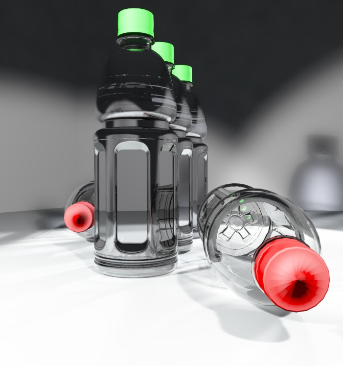 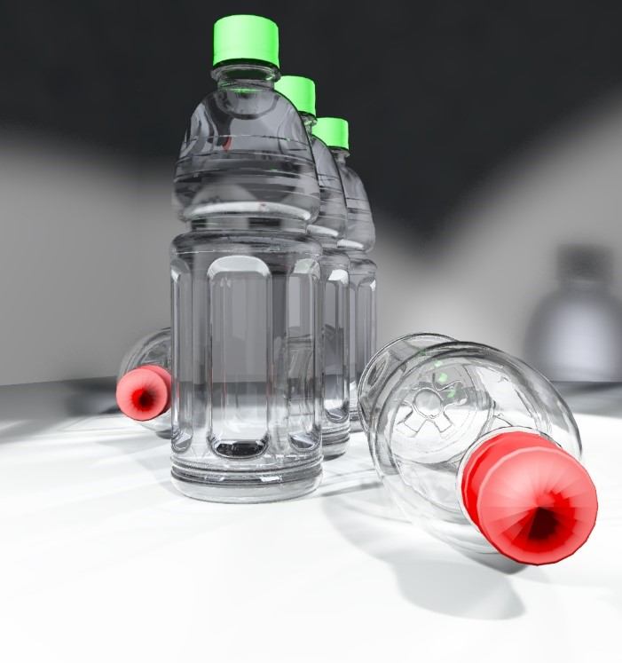 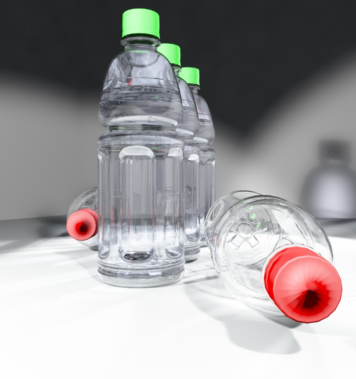 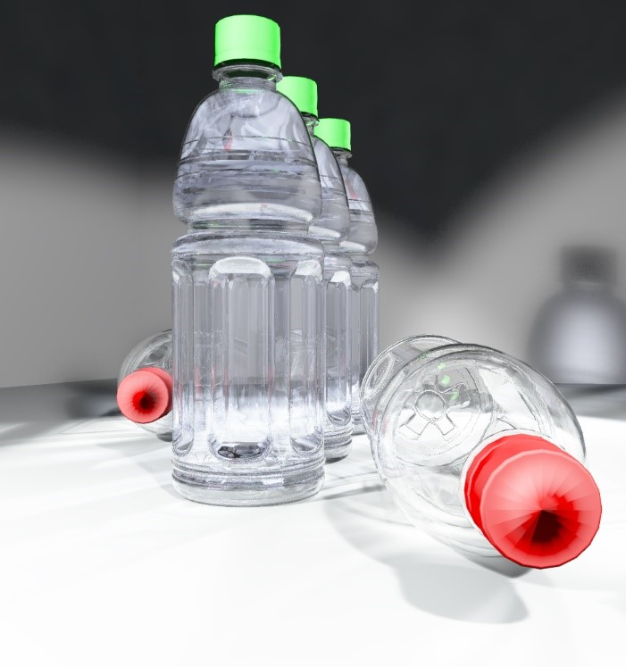
Top to
Bottom : Refraction Depth = 5,8,12,16
|
| Stroke tolerance
|
Controls the number of triangles curved surfaces are
broken into before being rendered. Smaller values produce smoother results but
at the expense of render time. Stroke Tolerance may be defined in pixels or
physical units. Stroke tolerance may be set as a distance in meters or pixels
where the latter is used the results will be view-dependent, that is if the
camera is closer to curved surface at render time will result in finer stoker
tolerance than when the camera is further away.
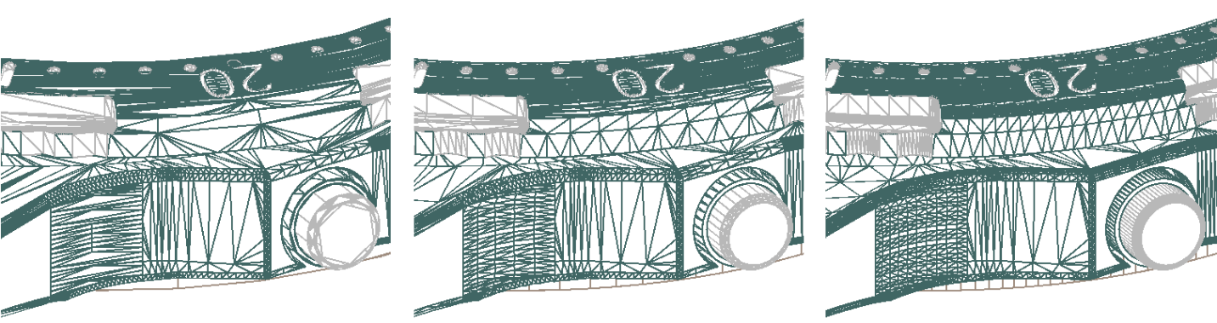
Left to
Right: Stroke Tolerance = 5, 0.5, 0.1
|
| Depth of Field
|
If enabled camera blur will be used to mimic the
depth of field effect. This is done as a post-process with very little
overhead. The point that is in focus is based on the focal distance and is the
distance from the eyepoint to the camera target.
|
| Blur
|
Shows the amount of blur applied when the Depth of
Field is enabled values can be above 100%.
|
| Blur Rendering Method
|
Options are Distributed ray-tracing, Hybrid 2.5D,
and Fast Hybrid 2.5D.
-
Distributed RayTracing - Used to render
Motion blur and depth of field. This method is a physically accurate approach
that converges towards the exact solution as the number of samples per pixel
increases.
-
Hybrid 2.5D - is a method that is
totally noise-free and much faster to compute. Computation time is not very
dependent on scene complexity.
Note: Hybrid
2.5D is not compatible with network rendering, due to the way this algorithm
works. The distributed ray-tracing blurring method will be enforced when you
enable network rendering.
-
Fast Hybrid 2.5D - Uses a new algorithm
for depth of field generation. It is based on image blur like Hybrid 2.5D but
uses a faster color spreading algorithm and works in conjunction with
distributed ray tracing. Usually, several passes are required to get all the
distributed raytracing noise smoothed out. Systematic object anti-aliasing is
incorporated inside Fast Hybrid 2.5D. Therefore, anti-aliasing settings become
linked to the depth of field settings. This means that only systematic
anti-aliasing becomes available, and the minimum number of rays per pixel
becomes equal to the number of the depth of field passes (changing either of
them changes both values).
|
| Camera Projection
|
Options are From View, Spherical and Cylindrical.
For rendering panorama images, you can use cylindrical or spherical with
recommended aspect ratio of 2:1 for example 5000 x 2500 or 10000 x 5000 pixels.
|
| Shadows
|
If selected shadows are rendered.
|
| Ignore Default Lighting
|
If enabled, will ignore default lighting.
|
| Ignore Open Elements and Text
|
If enabled, will prevent text and open elements from
being rendered, our default is to have this option enabled.
|
| Ignore Glow in Materials
|
If enabled, will ignore the
"glow" material in the DGN from rendering. This will reduce
the rendering time.
|
| Render Geometry Outside View
|
If enabled, will make sure the entire scene is sent
to the render engine. If not enabled some geometry behind the camera may not be
rendered. Geometry that is crossed by the camera's view frustrum will always be
included.
|
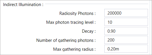
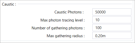
| Compute Physically Accurate Caustics
|
If enabled, will cause the render engine to render
caustic effects. The accuracy of the caustics can be improved by increasing the
number of Caustic Photons used.
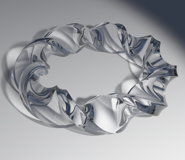 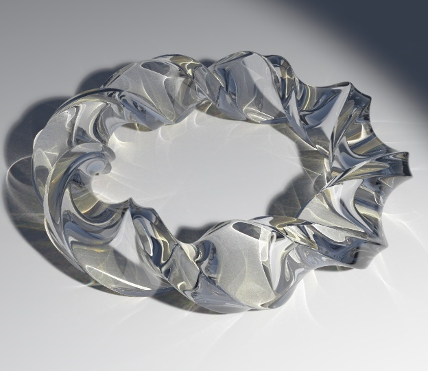
Top:
Without Caustics | Bottom: With Caustics
|
| Render PBR materials as Legacy Equivalent
|
If enabled, will convert PBR materials to legacy
and send to the ray tracer at render time.
|