Raster Line Style Example
In this example, you will create a simple stroke that will be used as a sketchy line style. The main advantage to this workflow is that you can also create a vector based point symbol which can be used when raster line styles are not supported such as printing to PDF or in older versions of MicroStation.
Setting Up the Design File
- Using the seed file 3D Imperial Design.dgn, create a DGN file, named my_stroke.dgn.
- Open the Design File Settings dialog ( ).
- In the Working Units section, set the following:
- In the Grid section of Design File Settings dialog, set following:
- Click OK.
- Change the background color to white using the following steps:
- In the File tab, click Save Settings.


Creating a Stroke Pattern
To have a baseline and a known scale for our raster, let us assume the brush stroke will be about 4 inches or 100 mm long and about ½ inch or 12 mm wide at its widest point.
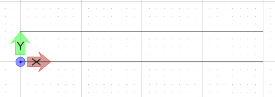
- Set the view window in Top view.
- Start the Place Line tool ().
- Press <Enter> to open the key-in window.
- In the Key-in window,
enter
XY=0 and press <Enter>.
The first end of the line is placed at origin.
- In the Place Line tool settings window, enter 4 in the Length field and 0 in the Angle field.
- Enter a data point to place the line.
- Now start the Move/Copy Parallel tool ( ).
- In the tool settings window, make the following settings:
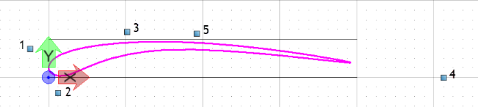
- Select the line element and enter data point above the line to place copy of the line at a distance of 0.5 inches.
- Start the B-spline by Points tool ( split button).
- Make the following settings in the tool settings window:
- Place a closed B-spline using five control points, something like shown below. You can place them roughly first and manipulate the handles later to get the desired shape.
- From the View Control
toolbar, select
View Attributes, and from the
View Attributes dialog that opens,
turn on the
Fill toggle.
The shape is created.
Rasterizing the Shapes
- First resize the view such that the shape just fits in the view as shown below. This will eliminate the need for having to crop the raster later.
- Open the Vue Rendering dialog () make the following settings:
- In the Vue Rendering dialog, click the Render button.
- Once the render is complete, move the Brightness slider all the way to the left so that stroke appears nice and dark.
- Click the Save Image to File icon.
- In the Vue Rendering dialog, select Save Image to file and set file type to PNG and name the image my_stroke.png.
- Click Save.


Creating Line Style Resource File
- Open the Line Style Editor dialog ( ).
- In the Line Style Editor dialog, select to open the Create Line Style Library dialog.
- In the Create Line Style Library dialog, navigate to the folder where you want to save the custom line styles and name the file My_LineStyles.rsc.
- Click Save.
- In the Line Style Editor dialog, select to save the newly created resource file.
- Open the Configuration Variables dialog ( ).
- Select the Symbology category and from the configuration variable list, double-click the MS_SYMBRSC configuration variable.
- In the Edit Configuration Variable dialog, add the path of your new .rsc file.
- Click OK to close the Edit Configuration Variable dialog and again click OK to close the Configuration Variables dialog.
- In the Alert window that pops-up, click Yes.
- Click Save Settings in the Quick Access Toolbar and exit and restart MicroStation.
Creating New Line Style
- Open my_stroke.dgn.
- Open the Line Style Editor dialog ( ).
- Select to open the Open Line Style Library dialog.
- Select the My_LineStyles.rsc that you created earlier and click Open.
- Select
.
A new line style is created.
- Select to open the Select Raster Line Style File dialog.
- Navigate to the location where you saved the my_stroke.png file and double-click on the file to open it.
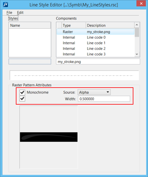
- In the Line Style Editor dialog, make the following settings:
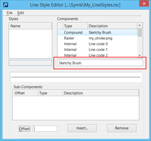
- Select .
- In the field below Components, change the description from new compound component to Sketchy Brush and press <Enter>.
- Select .
- In the field below the
Name list box, rename
Unnamed to
Sketchy Brush and press <Enter>.
Observe that the name in the list box also changes to Sketchy Brush.
- Now select the Compound Sketchy Brush and click the Insert button to open the Select Component dialog.
- In the Select Component dialog, scroll the list box and select the Raster my_stroke.png and click OK.

- Select .
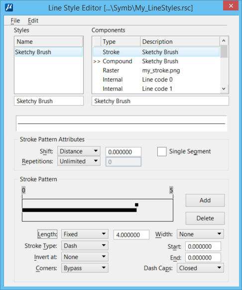
- In the field below Components, change the description from new stroke component to Sketchy Brush and press <Enter>.
- Click
Add and make the following settings in the
Stroke Pattern section:
- Length - Fixed and enter 4 in the adjacent field.
- Width - None
- Stroke Type - Dash
- Start - 0
- Invert at - None
- End - 0
- Corners - Bypass
- Dash Caps - Closed
Note: The length is in Master Units and will be used in many different design files with varying units for scaling purposes. In this example, we are assuming a baseline in inches so this would be 4 inches and scaled accordingly. To make the scaling based on real world units, the line styles can be imported into a DGN and saved as a DGNLib.
- In the Line Style Editor, select to save the line style.
Optimizing Geometry for Point Symbol
- Select the Mesh from Element tool ( ).
- Select the stroke pattern element that you created.
- Enter a data point.
Since we want the point symbol to appear solid and a mesh element does not have area fill option, you need to drop the mesh and create a complex shape.
- Start the Drop Element tool ( split button).
- In the Drop Element tool settings window, turn on the Solids check box and select To Surfaces from the adjacent drop-down list.
- Select the element.
- Right-click on the element and select Properties.
- In the Properties dialog, select the drop-down adjacent to the Fill property and from color table that pops-up, turn off No Fill and select color 0.


Creating Vector based Line Style using Point Symbol
- In the Line Style Editor dialog, select .
- In the field below Components, change the description from new point component to Sketchy Brush and press <Enter>.
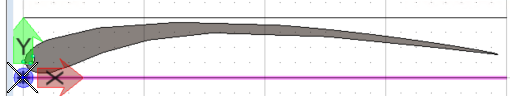
- Start the Define Cell Origin tool ( split button ).
- Define the origin for the point cell at 0,0 where you see the ACS Triad as shown below.
- Reset to end the Define Cell Origin command.
- Select the complex shape.
In the Line Style Editor dialog, observe that the Create button at the bottom enables.
- Click the Create button.
- In the Create Point Symbol dialog that opens, enter Sketchy Brush in the Name field. and click OK.
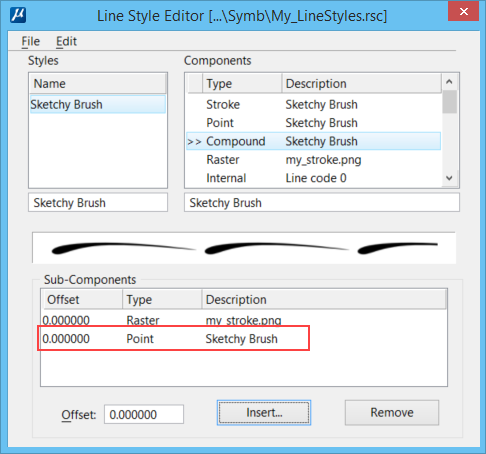
- Now select the Compound Sketchy Brush from the Components list box and click Insert.
- In the Select Component dialog, scroll the list box and select the Point Sketchy Brush and click OK.
Associating the Stroke with the Point Symbol
- In the Line Style Editor dialog, select Point Sketchy Brush from the Components list box.
- Click Base Stroke Pattern.
- In the Base Stroke Pattern
dialog, select
Sketchy Brush and click
OK.
A line black appears below the Base Stroke Pattern button.
- Click the line and then click the Select button.
- In the Select Point Symbol
dialog, select
Sketchy Brush is selected and click
OK.
The pattern is previewed in the Line Style Editor dialog.
- In the Justify drop-down, select Left.
- Select to save the resource file.

You are now ready with the line style.
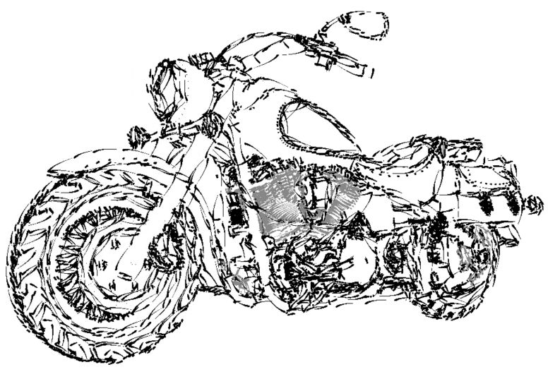
Testing the Sketchy Brush Line Style
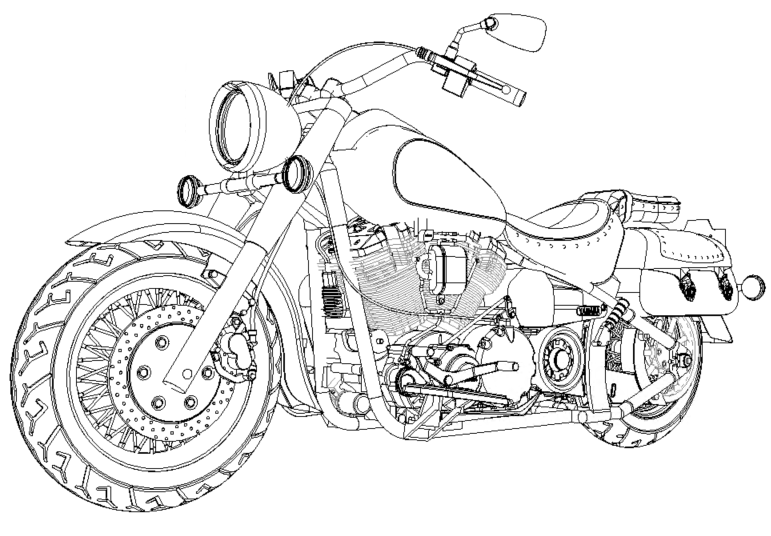
- Press <Ctrl+A> to select all the elements in the model.
- Open Line Styles dialog ( ).
- In the Line Styles dialog, select the Sketchy Brush line style that you created in the above procedures.
- In the dialog, turn on the Scale factor check box and in the adjacent field, enter the scale factor 0.1.
- Click on the preview of
the line style at the bottom of the dialog to activate the line style. The
output looks as shown below.
Note: For a more hand drawn look, use the Element Selection tool to select by level and change the scale factor. For example, select the Tire level and change the Scale factor to 0.2 and click on preview in the Line Styles settings dialog to activate using the new scale factor. Try making some of the levels have smaller scale factors and some with larger.

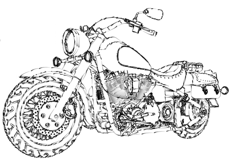
Testing the Vector Based Line Style
- Open the Configuration Variables dialog.
- Click New.
- In the New Configuration Variables dialog, type MS_NO_RASTER_LINESTYLE in the Variable field and 1 in the New Value field.
- Click OK in the New Configuration Variable dialog and again click OK in the Configuration Variables dialog.
- Click Yes in the Alert window that pops-up.
- Click the Update View button in the View Control toolbar to observe the vector based line style displayed.