| Flood icon |
Edges bound the area enclosed by elements that either touch one another or whose endpoints fall within the Maximum Gap. Selection sets can be used to select the elements required to enclose the flood area. This is somewhat akin to the flood fill tool in many paint programs. Where a selection set is not used, each element, or a part of each element, to be used to create the region must be visible in the view. For example, where a group of lines (not line strings) create a graphically closed shape, but some are not within the view, then no region is created and the following error message results — Error - No enclosing region found.
|
| Union icon |
Edges bound the union of two or more closed planar elements (shapes, ellipses, circles, or complex shapes). Where more than two elements are involved, use <Ctrl-data point> to select the extra elements.
|
| Intersection icon |
Edges bound the intersection of two or more closed planar elements (shapes, ellipses, circles, or complex shapes). Where more than two elements are involved, use <Ctrl-data point> to select the extra elements.
|
| Difference icon |
Edges bound the difference of two or more closed planar elements (shapes, ellipses, circles, or complex shapes). Where more than two elements are involved, use <Ctrl-data point> to select the extra elements.
|
| Fill Type |
Sets the Active Fill Type.
- None — If on, the complex shape is not filled.
- Opaque — If on, the complex shape is filled with the Active Color.
- Outlined — If on, the complex shape is filled with the Fill Color.
|
| Fill Color |
(Fill Type set to Opaque or Outlined only) Complex shape is filled with this color (and optional gradient) if the Fill Type is Outlined. When Fill Type is Opaque, Fill Color displays the Active Color, which can also be set from this location. When Fill Type is None, the Fill Color option is disabled (dimmed).
|
| Keep Original |
If on, the original elements remain in the design. |
| Associative Region Boundary |
If on, the region boundary retains association with the elements used to create it. If one of the original elements is modified, then the boundary element updates to reflect the modification. |
| Ignore Interior Shapes icon |
(Flood icon selected only) If selected, interior shapes are ignored when the region boundary is calculated. |
| Locate Interior Shapes icon |
(Flood icon selected only) If selected, closed elements inside the selected area are included as part of the new complex shape. |
| Identify Alternating Interior Shapes icon |
(Flood icon selected only) If selected, alternating areas are flooded where shapes are nested inside one another. |
| Locate Interior Text icon |
(Flood icon selected only) If on, any text or dimensional text inside or overlapping the selected area is avoided. |
| Dynamic Area Locate icon |
(Flood icon selected only) If on, the area to be included in the region displays dynamically as you move the screen pointer over the view. |
| Max(imum) Gap |
(Flood icon selected only) Sets the largest distance allowed between consecutive elements. If zero, only elements that connect can be added. |
| Text Margin |
(Flood icon selected only) Sets the margin to be left around any text or dimensional text that is included in the selected area. |
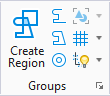
 Used to create a complex shape which is a closed complex element that can be manipulated as if it were a single primitive element. You can create regions from either of the following: