Modify Solid Entity (Legacy)


(3D only) Used to manipulate faces, edges, or vertices of a solid by pushing or pulling them interactively.
Icons in the tool settings let you select from All, Face, Edge, or Vertex, when selecting the item to modify. These determine what you can modify and how you can select them.
The AccuDraw Compass automatically orients itself depending upon which entities are selected (single and multiple selections). The automatic AccuDraw orientations may be manually reoriented at any time to achieve desired outcomes.
Pressing and holding the <Ctrl> key allows you to select and deselect multiple entities. Clicking Reset changes the selections by replacing entities with adjacent ones.
Multiple selection works only with entities of a single solid. Results may vary depending upon the complexity of the resultant solids.
| Setting | Description |
|---|---|
| All (icon) |
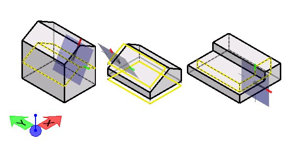
Lets you select a visible face, or any edge or vertex on a solid in the view. |
| Face (icon) |
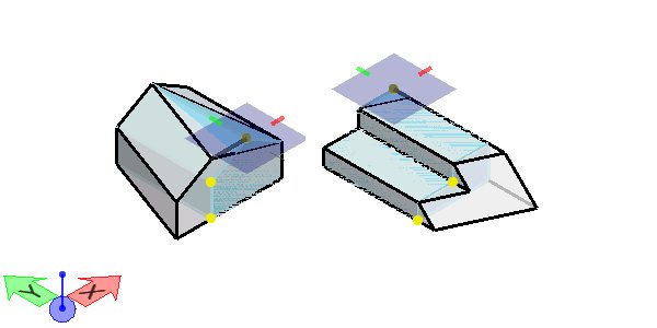
Lets you select faces on any identified solid in the view. By default the nearest face is selected, with Resets letting you select hidden faces on the same solid. AccuDraw orients the drawing plane perpendicular to the last selected face, so in the example below the Y and Z axes are coplanar (to the face), and the push-pull is along the X axis. |
| Edge (icon) |
Lets you select any edge on any solid in the view. AccuDraw orients the drawing plane perpendicular to the last edge selected, as shown below. |
| Vertex (icon) |
Lets you select any vertex on any solid in the view. Because a vertex is a point, AccuDraw has no reference plane to reorient itself to. Instead, AccuDraw orients the drawing plane to the last used orientation. The Vertex icon differs from other multiple selections in how vertices are detected. For instance, if an edge is selected near its midpoint, both its vertices are highlighted. If only one is needed, then moving the pointer nearer to it causes the other to not be highlighted. If both are highlighted and selected, either may be deselected by pressing the <Ctrl> key. |
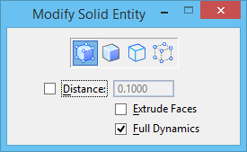
| Distance |
If on, sets the distance that the face, edge, or vertex, is to be modified. |
| Extrude Faces |
(All or Face selected only) If on, the selected face is extruded. If off, the selected face is moved and adjusted along with the adjacent sides. |
| Full Dynamics |
If on, dynamic display shows the modified element as you move the pointer. If off, an arrow graphic indicates the direction and extent of the modification. |