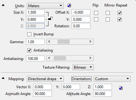
| Units |
Sets the mapping units.
- Master — Maps the image to a size defined in real world units — the master units for the model.
- Surface — (Mapping set to Parametric only) Stretches the image to fit the surface to which it is assigned.
- Meters
- Millimeters
- Feet
- Inches
|
| Dynamically Adjust Map icon |
Available only when a material previously has been assigned to a level/color. Activates the Dynamically Adjust Map tool, which lets you adjust the position of a map interactively. |
| Size X, Y, Z |
Sets the map's size in the x, y, and z (3D procedural textures only) axes. Used to repeat or tile the map on elements. When the lock is enabled, any changes to the X, Y, or Z settings is automatically reflected in changes to the other settings to maintain the aspect ratio of the original image or procedural texture.
|
| Offset X, Y, Z |
Sets the offset of the maps from the x, y, and z (3D procedural textures only) axes. |
| Rotation |
Sets the angle at which the selected map is rotated when applied to elements in the model. Useful examples include angled wood paneling or tiles. |
| Flip (X, Y) |
If on, flips the orientation of the map image about the x and/or y axis. |
| Mirror (X, Y) |
If on, each repetition or tile of the map image is a mirror reflection of adjacent tiles along the x and/or y axis. |
| Repeat (X, Y) |
If on, the map is tiled or repeated along the selected axis, where the element is larger than the map. |
| Transparent Background |
(Pattern maps only) If on, the pattern map has a transparent background. The background is defined as all pixels that have the same color as the image's upper left pixel. |
| Invert Bump |
(Bump maps only) If on, the bump map is inverted — the "hills" (bumps) become "valleys" and vice-versa. |
| Use Cell Colors |
(Geometry maps only) If on, the geometry map is displayed with the colors from the cell elements. This is true even in the cached visible edge display mode. If off, and if the Use Color From Materials check box in the Display Styles dialog is on, the geometry map is displayed with the material color; otherwise with the underlying element’s color. |
| Gamma |
You can set the gamma for each texture used in creating your material. The default gamma used to render is 1.7. By lowering the gamma of the texture you can prevent your textures from appearing overly bright and lacking contrast. |
| Antialiasing |
If on, turns on the Antialiasing function for the selected image layer to provide texture filtering and produce smoother rendered results. Antialiasing samples the image’s pixels in texture space (as opposed to screen or render space) and averages them based on strength. |
| Texture Filtering |
Texture filtering is now controlled on a per material basis. Texture filtering options are:
- Nearest — disables filtering of the image, the actual pixels of the image are sampled.
- Bilinear — samples neighboring pixels vertically and horizontally, producing smooth (blurry) results.
- Bicubic — samples all adjacent pixels providing the smoothest result.
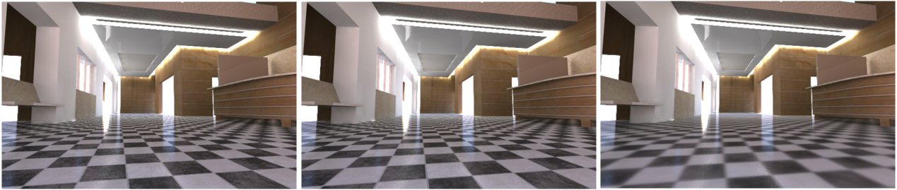
Left: Without Texture Antialiasing and Filter set to Nearest; visible noise in floor near back wall. Center: Texture Antialias enabled and Filter set to Bicubic for smoother results. Right: Texture Antialias enabled and Filter set to Bicubic with Antialiasing Strength set to 2000.
|
| Low Value |
(Displacement maps only) Allows you to remap the range of tones in an image. For instance, if you are using an image as a displacement map you might want the darkest pixels to push the surface in and the brightest pixels to push it out. By default the pixels of an image range from 0 to 100%, which means that none of the pixels would yield a value to push the pixels inward. By setting the value range from -100% to +100% the image is effectively remapped so that the black pixels create a negative displacement, the white pixels create a positive displacement, and the mid-tones are "neutral".
The Low Value determines the effective value of pixels that have a true value of 0, 0, 0 (RGB).
|
| High Value |
(Displacement maps only) Allows you to remap the range of tones in an image. The High Value determines the effective value of pixels that have a true value of 255, 255, 255 (RGB). See Low Value. |
| Origin Relative to Object |
(3D procedural textures only) If off, the texture is applied to each pixel using only its position in space. If on, the position is calculated relative to the origin of the individual object, or the origin of the cell where a number of elements are grouped. Note: When animating a procedurally mapped object, this setting should be on, to avoid the phenomenon of the object "sliding" through the texture and producing a different mapping for each frame.
|
| Mapping |
Sets the mapping mode.
- Parametric — The image file is mapped to the element, relative to the element's origin. Thus, if you rotate an element that has the material assigned to it, the map rotates with it.
- Planar — Aligns the horizontal axis of the map with the horizontal plane (x,y) of the DGN file. The image then is tilted to match the slope of the selected surface. This mode is useful for materials attached to SmartSolids.
- Elevation Drape — "Drapes" an image file over all elements contained in a view. Useful for mapping (scanned) aerial photography to a 3D digital terrain model.
- Directional Drape — Mapping is applied relative to the direction specified by the Orientation setting.
- Cubic — Uses a six-sided cube as the map shape.
- Spherical — Approximates reflective surfaces by considering the environment to be an infinitely-distant spherical wall.
- Cylindrical — Wraps the map along the outside of a cylinder.
- Solid — (3D procedural textures only) Solid mapping is used with procedural materials and unlike 2D image-based textures, works only in 3D texture space.
|
| Orientation |
(Mapping set to Directional Drape) Sets the orientation for the directional drape. Options are: Top, Front, Right, Bottom, Back, Left, Custom. |
| Vector X, Y, Z |
(Mapping set to Directional Drape, Orientation set to Custom) Sets the direction of the projection in the x, y, and z axis. |
| Define Drape Direction by Points icon |
Lets you set the directional drape vector by entering two data points. |
| Azimuth Angle |
(Mapping set to Directional Drape) Sets the azimuth direction of the directional drape. Azimuth values may be keyed in, or you can use the settings window below to interactively set the direction by clicking the compass at the required direction, or clicking and dragging the indicator as required. |
| Altitude Angle |
(Mapping set to Directional Drape) Sets the angle of the directional drape. Altitude angle values may be keyed in, or you can use the settings window below to interactively set the altitude by clicking and dragging the indicator to the required altitude setting. |
| Capped |
(Mapping set to Cylindrical) If on, cylinder is capped. |