Visible Edge Processing Configuration Variables
The visible edges configuration variables allow the user to control the visible edge calculation settings. These variables either provide default settings or override the existing setting values.
The following configuration variable provides default settings:
- MS_VISEDGE_DEFAULTS - Controls the default settings. The default settings are otherwise extracted from the design file. You can still change these values through the user interface, as desired. The default settings are applied when you open a design file and do a save setting (File > Save Settings).
The following configuration variables can be used as overrides. If used, these values will always take precedence over the conventional settings and the corresponding user interface item will be dimmed. The tooltip for the dimmed setting will indicate the details of the configuration variable override.
| Configuration Variable | Description |
|---|---|
| MS_VISEDGE_OVERRIDES | Controls all of the visible edge processes. |
| MS_CVE_VISEDGE_OVERRIDES | Controls the Cached Visible Edge (CVE) generation. |
| MS_PLOT_VISEDGE_OVERRIDES | Controls the plotting visible edge filtering. |
| MS_EVE_VISEDGE_OVERRIDES | Controls export visible edge and reference file merge processing. |
Each of the above variables can specify one or more of the settings listed below by including the keywords and values in a comma separated list. The keywords are all directly related to the (English) items in the visible edge setting dialogs. Following are some example of override settings:
- To override the Calculate Intersections and Accuracy settings for all visible edge processes, set MS_VISEDGE_OVERRIDES to CalculateIntersections=true, Accuracy=Medium
- To override Remove Smooth Edges option for Cached Visible Edge processing only, set MS_CVE_VISEDGE_OVERRIDES to RemoveSmoothEdges=true
- To force plotting to use exact method and tolerance of 1 inch for plotting only, set MS_PLOT_VISEDGE_OVERRIDES to Method=Exact, Accuracy=1 inch
Visible Edge Overrides
The following table lists the keywords and their values for the visible edges overrides that can be used in the visible edge processing configuration variables:
| Keyword | Values | Notes |
|---|---|---|
| Method | Fast, Exact | Recommended value is Exact |
| PlotMethod | Fast, Exact | . |
| CalculateIntersections | True, False | . |
| RemoveSmoothEdges | True, False | . |
| ExpandCustomLineStyles | True, False | . |
| ProcessTextAndDimensions | True, False | . |
| UseColorFromMaterial | True, False | . |
| ForceHiddenEdgesOn | True, False | . |
| DoTransparencyThreshold | True, False | . |
| TransparencyThresholdValue | 0-1.0 | If DoTransparencyThreshold=true |
| Accuracy | Low , Medium, High, ToTolerance | Recommended value is ToTolerance |
| Tolerance | Distance (see section below) | . |
| OcclusionTolerance | Distance (see section below) | Only available as override. |
| VisibleEdgeColor | 0-255 | Specifies visible edge color. Not applicable to MS_PLOT_VISEDGE_OVERRIDES. |
| VisibleEdgeStyle | 0-7 | Specifies visible edge style. Not applicable to MS_PLOT_VISEDGE_OVERRIDES. |
| VisibleEdgeWeight | 0-31 | Specifies visible edge weight. Not applicable to MS_PLOT_VISEDGE_OVERRIDES. |
| HiddenEdgeColor | 0-255 | Specifies hidden edge color. Not applicable to MS_PLOT_VISEDGE_OVERRIDES. |
| HiddenEdgeStyle | 0-7 | Specifies hidden edge style. Not applicable to MS_PLOT_VISEDGE_OVERRIDES. |
| HiddenEdgeWeight | 0-31 | Specifies hidden edge weight. Not applicable to MS_PLOT_VISEDGE_OVERRIDES. |
Distance Settings
When setting tolerances, it is possible to use either the traditional MU:SU:PU (Master Units, Sub Units, Positional Units) setting, or to specify the units explicitly. Since the MU:SU:PU setting is dependent on the design file settings, the explicit units are generally preferable. For example,.1 Millimeters or .001 Inches can be used to set a consistent distance in files with any design file setting.
Occlusion Tolerance
The OcclusionTolerance setting is provided as an additional control for the visibility of ambiguous edges. This setting controls the visibility calculation for adjacent, coincident geometry. For models with overlapping, and therefore ambiguous geometry, this setting can be important for producing consistent results. Consider the following example:
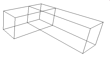
The lines at the top of these slabs are ambiguous as they coincide with the surfaces from the adjacent slabs. Their display is not determined reliably when hidden lines are displayed, as the display hardware cannot distinguish the visibility of this type of anomaly.
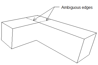
The Occlusion Tolerance controls the visibility of such ambiguous edges. If the distance between the edge and the occluding geometry is less than this tolerance then the edge will be treated as visible. In models with an overlapping geometry, setting this tolerance to a small distance (.001 millimeter) can stabilize the display of the edges, which might otherwise be inconstantly hidden. Using higher values may cause the geometry that should be hidden to become visible.
Occlusion Tolerance values can be entered inMU:SU:PU format or with explicit (plural) unit names (separated by space). Explicit units are preferred, as the value will be interpreted consistently in files with different unit settings. For example, .001 Millimeters and .0001 Feet, are valid values.
Recommended Settings
The Exact method is recommended for all visible edge processing. This setting controls whether curved geometry is represented precisely or approximated with strokes or facets. The exact method is only marginally slower, but produces superior results.
The Accuracy and Tolerance settings are not critical when the Exact method is used. The Accuracy setting is simply a method for controlling the tolerance as a fraction of the overall model (or reference attachment) size. To produce most consistent results, it is recommended that Accuracy be set to ToTolerance and tolerance be specified explicitly. A value of .01 Millimeter should produce acceptable results in all models.