To Add Dimensional Constraints to a Profile
-
In the Dimensions toolbox, select the Element Dimensioning tool.

- Click the Dimension Element icon in the tool settings, and set Alignment to Drawing and Location to Automatic.
-
Select the vertical edge at the right of the profile.
The Element Dimensioning tool settings window now display a Constraint field.
- Select the Constraint check box and in its field, type W1.
-
Move the pointer to the right of the profile and enter a data point to complete the dimension.
The status bar displays DOF=3.
-
Repeat for the bottom edge of the profile, naming the constraint L1.
The status bar displays DOF=2.
-
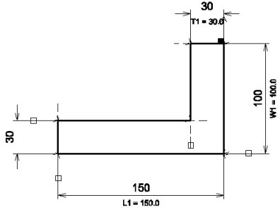
Similarly, dimension the topmost edge of the profile to specify its thickness, naming the constraint T1.
The status bar displays DOF=1.
-
Dimension the left edge of the base of the profile, this time selecting the existing constraint T1, from the constraints list box in the tool settings.
The status bar displays DOF=0. In other words, the profile is fully constrained.