To Create a Point Symbol Component (by Adapting an Existing Component)
-
In the Components list box, select the point symbol component to adapt.
The controls for working with point symbol components are displayed.
-
From the Edit menu, choose Duplicate.
The component is duplicated. The duplicate is automatically selected in the Components list box, and a sample line with the point symbol component, the base stroke pattern, and the point symbol itself are displayed.
- (Optional)
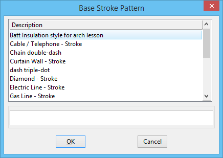
Click the Base Stroke Pattern button.
The Base Stroke Pattern dialog opens.
- (Optional) In the Base Stroke Pattern dialog, select a stroke pattern component on which to base the new point symbol component, and click the OK button (or double-click the desired component).
- (Optional)
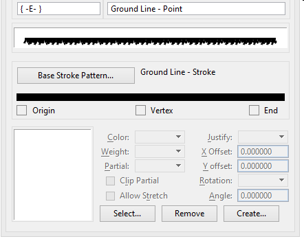
Back in the Line Style Editor dialog, select the stroke with which you want to associate a point symbol by first having the desired Point Line Style displayed.
The selected stroke is highlighted.
- (Optional)
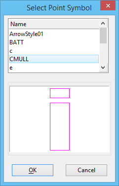
Click the Select button at the bottom of the dialog.
The Select Point Symbol dialog opens. All point symbols in the open line style libraries are available for selection. Follow the steps in To create a point symbol to create additional point symbols and make them available for selection.
- (Optional)
In the Select Point Symbol dialog, select a point symbol, and click the OK button (or double-click the desired point symbol).
Back in the Line Style Editor dialog, the resulting point symbol component is displayed below the list boxes.
- (Optional)
Specify the association between the point symbol and the selected stroke:
To put the origin of the associated point symbol on the midpoint of the stroke, choose Center from the Origin option menu.
or
To put the origin of the associated point symbol on the starting point (left end) of the stroke, choose Left from the Origin option menu.
or
To put the origin of the associated point symbol on the ending point (right end) of the stroke, choose Right from the Origin option menu.
To specify an additional point symbol origin horizontal offset distance (from the justification point set on the stroke in the previous step), key in the desired distance, in master units in the direction of the stroke pattern (x-axis), in the X Offset field.
To specify an additional point symbol origin vertical offset distance (from the justification point on the stroke), key in the desired distance, in master units in the direction perpendicular to the stroke pattern (x-axis) and its plane, in the Y Offset field.
To set the point symbol rotation angle, key in the desired angle, in degrees, in the Rotation field.
- (Optional) Repeat steps 5-8 to associate point symbols with additional strokes.
- (Optional) In the field below the Components list box, key in the component description.
- From the File menu in the Line Style Editor dialog, choose Save.