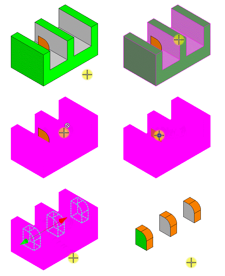
To Create a Cut Using an Element as the Profile
-
Select the Cut Feature tool.
The Cut Feature tool settings window opens.
- Modify the settings for the cut as required.
- Select the solid to cut.
-
Select the cutting element.
An arrow shows the directions for the cut. If Both Directions is selected, two arrows appear: a green arrow for the Through Direction, and a red arrow for the Back Through direction.
- Move the pointer until the arrow points in the desired direction for the cut, and enter a data point.
- Enter a data point to accept the cut.
- (Optional)
To select additional elements to use for cutting profiles, hold <Ctrl> and enter data points to select elements.

Upper left: Original geometry. Upper right: Resulting geometry when these settings are used: Cut Inside Profile on, Both Directions off, Through All Faces. Lower left: Resulting geometry when these settings are used: Cut Inside Profile on, Both Directions on, Through All Faces. Lower right: Resulting geometry when these settings are used: Cut Inside Profile off, Both Directions on, Through All Faces.

Left: The original geometry is a feature-driven Slab with a DD Design profile. When an open profile is used, such as the arc shown on the left, it is extended tangentially from its endpoints to intersect the solid. Right: Cut produced from this profile.
