Place Section Callout
 Used to place a section callout and, optionally, create a saved view and automate dynamic views. When saved views are added to a sheet, existing section callouts that have empty fields are updated with relevant information.
You can access this tool from the following:

You can create steps or gaps in the section callout by pressing and holding the <Ctrl> while creating the section callout. The steps created in the callout can be merged using the step handles provided on the steps.
| Setting | Description |
|---|---|
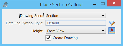
| Drawing Seed | Defines the seed file from which the detailing symbol style will be used for the section callout. |
| Detailing Symbol Style | Defines the detailing symbol style from the drawing seed. This style will be used by the section callout. |
| Show Detailing Symbol Style Settings (icon) | Opens the Detailing Symbol Styles dialog, in which you can create or edit a detailing symbol style. |
| Height | Sets the height or extent to which the callout clips the model. It has the following options: |
| Height (text field) | (Available only when the Height drop-down is set to User Defined) Enter the value of the height or extent to which the callout should clip the model. |
| Annotation Scale (icon) |
Used to turn on annotation scale. When this lock is on, the annotation scale is applied to the section callout. By default, the annotation scale is taken from the model's Annotation Scale setting. You can change it only in the model's properties in the Properties dialog. The exception is when the model's Propagate Annotation Scale property is off. In that case, the annotation scale can be controlled independently for each element via its properties. |
| Create Drawing | If on, the Create Drawing dialog opens after creating the section callout. This dialog is used for automating dynamic views. This check box is dimmed if the Drawing Seed option is set to none or if you are in an overlay file. |
| Tolerance | (Available only when a point cloud is referenced in the model) Allows you to enter the maximum distance, in working units, from each side of the cut plane to points that will be considered as part of the plane. |
| Project Points to Cut Plane | (Available only when a point cloud is referenced in the model) If on, the points within the specified tolerance range will be projected on the cut plane. If off, the points will be displayed at their real 3D location. |

