Detailing Symbol Styles
Detailing symbol styles allow an administrator to define standards for detailing symbols via symbology settings and placeholder fields. The benefit to using styles is that when you change a setting in a style, the change can be propagated to all detailing symbols using that style. You can create new detailing symbol styles in the Detailing Symbol Styles dialog ( dialog launcher). A default style is delivered in DrawingSeed.dgnlib. If you change the default style in the DrawingSeed.dgnlib, the icon next to the Default style in the Detailing Symbol Styles dialog changes. This indicates that the Default style is changed in the DrawingSeed.dgnlib. You can click the Update from Library icon to update the style from DrawingSeed.dgnlib.
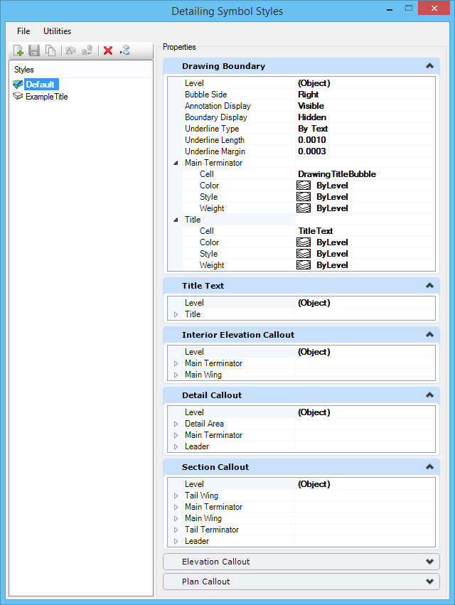
In addition to symbology settings, you can also control the cells used as bubbles in the callouts. For example, you can set the Title cell and Main Terminator cell to be used in drawing boundaries. These cells contain placeholder fields that are evaluated when the appropriate link is added to the detailing symbol.
The list of cells is populated from the annotation models in DrawingSeed.dgnlib. You can override this list of cells by providing custom cells.
If you do not want to associate a component to the callout, you can keep the Cell property of the component blank. However, in some cases, the callout becomes invalid. For example, in a drawing boundary, you cannot keep the Cell property of the Title component blank. If the Cell property is set to blank, then the status bar displays a warning message, saying that a style is invalid and when you try to save the style, you get an Information window saying the style is not valid. However, you can customize the validation rules for some of the components in your styles. Following table lists the components that require validation and that can have customized validations:
| Detailing symbol | Component | Validation required |
|---|---|---|
| Section Callout | Main Terminator | Customizable |
| Main Wing | ||
| Tail Terminator | ||
| Tail Wing | ||
| Leader | Yes | |
| Detail Callout | Main Terminator | Customizable |
| Leader | Yes | |
| Elevation Callout | Main Terminator | Any one of the two required |
| Main Wing | ||
| Drawing Boundary | Title | Yes |
| Main Terminator | Customizable | |
| Title Text | Title | Customizable |
| Plan callout | Main Terminator | Customizable |
| Main Wing | ||
| Tail Terminator | ||
| Tail Wing | ||
| Leader | Yes |
You can customize the validation rules using the configuration variable MS_DETAILINGSYMBOLSTYLE_REQUIREDSETTINGS. The syntax for the configuration variable is:
MS_DETAILINGSYMBOLSTYLE_REQUIREDSETTINGS Callout name1(component 1,component 2),Callout name2(component1,component 2)
For example:
MS_DETAILINGSYMBOLSTYLE_REQUIREDSETTINGS SectionCallout(MainTerminator,MainWing,TailWing),DrawingTitle(Main Terminator)
In this case, for section callout, the Main Terminator, Main Wing and Tail Wing will be validated along with the required Leader component. Whereas, for drawing boundary, the Main Terminator will be validated along with required Title component.
All the detailing symbol tools now use the same active detailing symbol style. This active style is the detailing symbol style used in the previous detailing symbol.