Modifying Parametric Elements and Features
During the design process it is not unusual to have design changes that require modifications to one or more elements in your design. With parametric modeling, compared to normal 3D modeling, these procedures are simplified. Parameters used to create the elements/features are retained in the design. When you edit a parameter, the element is regenerated.
Using Handles
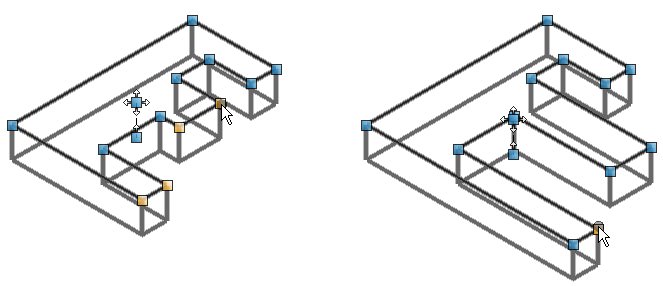
For "freestyle" modification of parametric elements and features, you can manually "push" and "pull" them, or move and adjust features such as holes and cuts by using handles that appear when you select the element or feature with the Element Selection tool. After you select an element or a feature, tooltips indicate what the handles are for. If you pause your pointer over a handle, a tooltip indicates that the handle either is part of the feature, such as "Hole Cbore./Csink. Diameter: 12.00, Diameter: 10.00" and can be used to modify it, or a Move/Copy handle such as "Move Slab by Point (Press <Alt> while dragging to toggle copy)." You can select the solid/surface with a Data Point, which displays the feature handles. When you modify an element interactively, you can select multiple handles to modify simultaneously. This is particularly useful with more complex elements, or those with multiple edges/faces that you want to manipulate together. To select multiple handles, use <ctrl+data point> on each required handle so that it is highlighted. To modify all the selected handles simultaneously, click and drag any of the highlighted handles.
In addition to interactive graphical modifications of elements and features, you can perform a number of operations via a reset (or right-click) menu.
The parameters of a copied parametric element (solid/surface) are bi-directionally associative with the parent parametric element. Hence to avoid changes made to single parametric solid to reflect on all copied parametric solid, by default they are kept non editable. However, in case if you want to make individual changes to a copied parametric solid or surface, then you need to select Show Input Element from the reset pop-up menu of Profile element in the Properties dialog or use the Show Input Feature tool (if required, you can hide the input element again). This will break the sharing of the parameters and allow you to edit that specific copy.
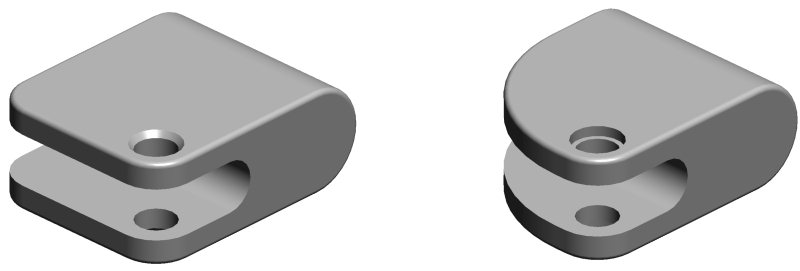
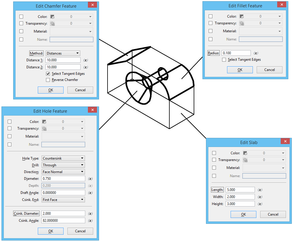
Consider the before and after images of this example; it consists of a rectangular solid to which various features have been added — fillets, a cut, and a countersunk hole. These features can be modified by editing their parameters.
Using Feature Modification Tools
Using the Merge Parametric Solids Option
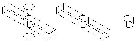
The Merge Parametric Solids check box is present in the tool setting of Trim Solid, Unite Solids, Subtract Solids and Intersect Solids operations. If this check box is turned on, the features applied to the participating solids are combined into the resultant solid. If it is turned off, the features of participating solids are preserved as separate elements. Consider the example of a slab with a filleted edge, trimmed by a similar solid element using the Trim Solid tool. Following images show the resultant solid that is created when Merge Parametric Solids is turned on and off:
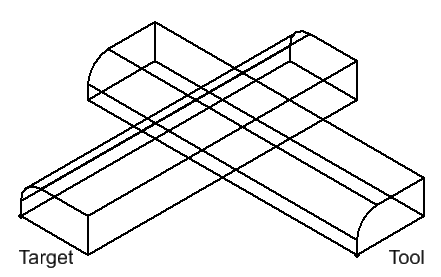

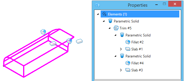
Left: Merge Parametric Solids set to off shows the resultant solid with features of the participating solids preserved individually | Right: Merge Parametric Solids is set to on shows the features of the participating solids merged into the resultant solid. The feature tree in the Properties dialog displays the elements and their features as nodes when the resultant is selected.
Using Variables
While each dimension for a feature can be edited individually, other options let you use variables to define dimensions, such that editing a single variable can propagate changes to all elements in the model that use that variable. Taking this further, you can use expressions to define variables. For example, you may want the width of a slab to be 1 meter plus one fifth of its length, and the Height to be one third of the Width. By assigning the appropriate equations to the Width and Height dimensions, only the Length parameter would be available for manual editing, with the remaining two dimensions automatically updated as per the expressions.