Workflow for Using Callouts in a Project
Following is a generic workflow for using the callouts in a project.
Using Callouts in a Project
- Place a callout in a 3D design model or in a drawing or sheet model.
The callout is automatically detected in the target design composition model.
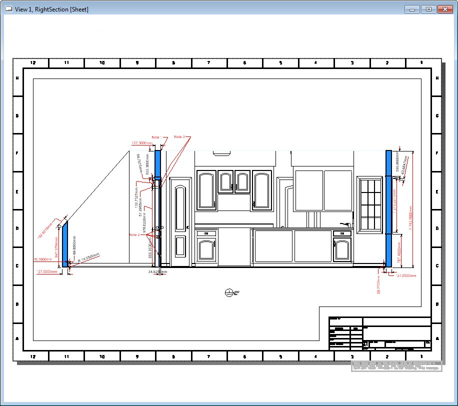
- From the Links tab of the Explorer dialog, drag the callout’s saved view onto another sheet.
- Add annotations, dimensions and other embellishments on the sheet.
- In the 3D design model, turn on the Markers icon from the View Attributes dialog to view the markers of the saved views in the project.
- Hold the pointer on a marker and select the Apply View tool. The saved view linked to the callout is applied in the 3D model.
- To make changes in the annotations, select the Open Sheet Model tool on the Mini toolbar to open the sheet model.
- Make the desired changes in the sheet model and select the Open Design Model tool in the Mini toolbar of the callout in sheet model to switch back to the 3D design model.
- Select the next marker to view the next callout location.
The result is that all of your project documentation is contextualized in 3D, at your control, automatically so that both the drawings in the sheet or drawing models and the 3D design model are easy to understand, interpret and update.