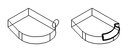
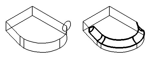
Sweep Edge Feature

Used to place a cut or protrusion along a path defined by edges of a feature-based solid, using one of the following as a profile:
- A profile element in the design or a parametric profile created with one of the DD Design tools.
- A cell or dimension-driven cell in the attached cell library, or another instance of one that is in the active design.
In addition:
- This tool makes cuts or protrusions along the edges of straight lines and circular edges such as curves, holes, or rounds.
- Cutting or protrusion profiles may be open or closed elements.
- When an open profile does not extend to the edge of the feature-based solid, it is extended tangentially to its end point until it intercepts the edge of the solid.
- Cutting or protrusion profiles need not be coincident with the feature-based solid on which the cut or protrusion is made.
- To delete cuts or protrusions, use the Delete Feature tool.
- To edit cuts or protrusions, use the Modify Parametric Solid or Feature tool, or edit within the Feature Manager. Editing an existing cut allows you to change the parameters used to construct it initially.
- With a dimension-driven profile, use the Modify Profile tool to modify the shape of the cut or protrusion.

| Setting | Description |
|---|---|
| Both Directions | If off, the cut/protrusion is made in one direction, relative to the profile’s surface normal. If on, the cut/protrusion is made in both directions relative to the profile's surface normal. |
| Mode | Sets the type of feature. |
| Method | Set the type of edge to use as a path. You can select one edge, a series of contiguous edges along which to cut, or points to define the cut. |
| Thickness | Sets the wall thickness for the profile. |
| Add Smooth Edges | (Selected Edges only) If on, edges that are tangentially continuous are selected. If off, only the selected section of the edge is selected. |
| Angle | (Circular Edge only) Specifies the angle for the sweep. |
| Cell | If on, the active cell is used as a profile. Enter the name of the cell, or click the Browse icon to select a cell. |
| Keep Profile | (Cell off only) If on, the original cutting/protrusion profile remains in the design. If off, it is removed. |
| Equation icons |
Lets you assign variables or equations to the corresponding setting. For more information, see Variables and Equations. |