Stencil 2D Elements on 3D Geometry
 Used to create renderable mesh geometry and place it on top of the underlying geometry. The tool creates a temporary depth map mesh based on the geometry that is displayed at the time the tool is used. You can also use the tool with a displayset. This allows the geometry created to span across levels or references depending on what is visible at the time you select the tool.
You can access this tool from the following:

The stenciled geometry is placed in a new model within the file and is automatically referenced into the current model. This allows you to easily detach the markings, edit the results or reprocess.
This tool is typically used for stenciling pavement markings on roadways using 3D elements.
The name of the tool settings window changes depending on which icon you select. For example, if you click the Stencil selected elements icon, the window name changes to Stencil Selected Elements.
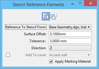

Stencil Reference Elements tool when the Stencil selection set or selected elements on 3D geometry icon is selected
| Setting | Description |
|---|---|
| Stencil 2D reference elements on 3D geometry |
Click this icon to select the 2D reference file that contains markings or elements from which you want to create the stencil. |
| Stencil selected elements |
Click this icon to create stencil mesh elements in the current file using selected element(s). This tool does not require a 2D file input; any closed shape in the current file can be used to create the stencil mesh. |
| Reference To Stencil From | (Available only when the Stencil 2D reference elements on 3D geometry icon is selected) Selects the 2D reference file that contains the markings or elements for creating the stencil. |
| Remove Original Elements | (Available only when the Stencil selected elements icon is selected) If on, the marking elements are deleted after the stencil is created. |
| Surface Offset | Sets the distance above the underlying geometry where you want the stencil geometry to be created. |
| Tolerance | Sets the stroke tolerance when you stencil curved elements. The stencil geometry is a mesh stroke and the stroke tolerance sets the smoothness of the resulting curves. |
| Direction | Sets the direction in which the stenciled element is projected. If set to Z, the stenciled element is always projected in the Z axis. If set to View, the stencil is projected in the direction of the view. |
| Add to Level | (Available only when the Stencil 2D reference elements on 3D geometry icon is selected) Sets the selected level from the file on which to place the stencil geometry. If the check box is off, the active level is used. |
| Apply Marking Material | (Available only when the Stencil 2D reference elements on 3D geometry icon is selected) If on, a non-shadow casting material is created and attached automatically to the geometry. The material will have a high diffuse value and use the element color for its color. |

