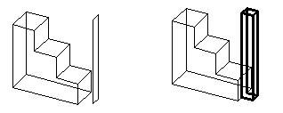
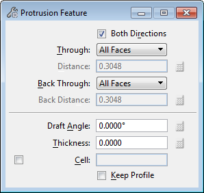
Protrusion Feature

Used to construct a protrusion on a solid using one of the following as the protrusion profile:
- A closed profile element (shape, complex shape, circle, or ellipse) in the design, or a parametric profile created with one of the DD Design tools.
- A cell or dimension-driven cell in the attached cell library, or another instance of one that is already in the active design.
In addition:
- To delete protrusions, use the Delete Feature tool.
- To edit protrusions, use the Modify Parametric Solid or Feature tool, or edit within the Feature Manager. Editing an existing protrusion allows you to change the parameters used to construct it initially.
- With a dimension-driven profile, use the Modify Profile tool to modify the shape of the protrusion.
| Setting | Description |
|---|---|
| Both Directions | If off, the protrusion is made in one direction, relative to the protrusion profile’s surface normal. If on, the protrusion is made in both directions relative to the protrusion profile's surface normal. |
| Through | Sets the limits of the protrusion.
|
| Distance | (Blind only) Sets the distance for a Blind protrusion. |
| Offset By/Move By | (Selected Faces only) Sets the distance to offset or move the protrusion from the original profile. |
| Back Through | Sets the limits of the backward protrusion direction (when protrusion is set to Both Directions). The options are the same as the Through options. |
| Draft Angle | Sets the angle of the projected protrusion profile relative to orthogonal. The Draft Angle value can be positive or negative. |
| Thickness | Sets the wall thickness for the protrusion profile. |
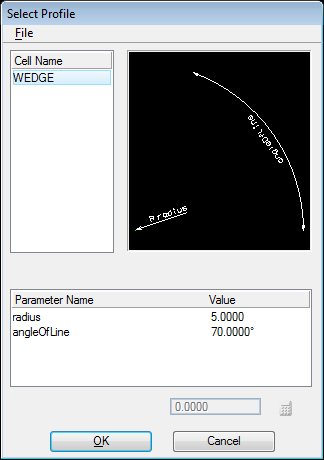
| Cell | If on, the active cell is used as a protrusion profile. Enter the name of the cell, or click the Browse icon to open the Select Profile dialog to select a cell. If the cell is dimension-driven, you can modify the parameters. |
| Keep Profile | (Cell off only) If on, the original protrusion profile remains in the design. If off, it is removed. |
| Equation icons |
Lets you assign variables or equations to the corresponding setting. For more information, see Variables and Equations. |