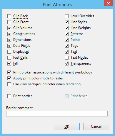
| Clip Back |
(3D files only) Toggles the display of elements and parts of elements located outside a 3D view's back clipping plane. If on, a back clipping plane is active in a view. |
| Clip Front |
(3D files only) Toggles the display of elements and parts of elements located outside a 3D view's front clipping plane. If on, a front clipping plane is active in a view. |
| Clip Volume |
Toggles the display of elements and parts of elements located outside a defined clip volume for a given view. If on, and a clip volume has been applied to the view, the view volume is restricted to the defined volume. If no clip volume has been applied to the view, it has no effect. |
| Constructions |
If on, construction elements are printed. |
| Dimensions |
If on, dimensions placed in the specified area are printed. |
| Data Fields |
If on, data fields are printed. |
| Displayset |
If on, you can select a group of elements to display in selected views. |
| Fast Cells |
If on, cells are displayed as outlines. Note: Turning on Fast Cells can decrease printing time.
|
| Fill |
If on, closed shapes with fill are printed with fill. |
| Level Overrides |
If on, printed element uses level symbology overrides. |
| Line Styles |
If on, elements are printed with their assigned line styles. |
| Line Weights |
If on, elements are printed with their assigned line weights. |
| Patterns |
If on, patterns placed in the specified area are printed. |
| Points |
If on, points placed in the specified area are printed. The default is specified in the printer driver configuration.
PRINT
ATTRIBUTES
POINTS
<
ON |
OFF
>
|
| Tags |
If on, tags are printed. |
| Text |
If on, text placed in the specified area is printed. |
| Text Nodes |
If on, text node indicators placed in the specified area are printed. |
| Transparency |
If on, elements are printed with their specified transparency. Transparency can only be printed in rasterized mode, except when using the PDF printer driver. In addition to full transparency support in rasterized mode, the PDF printer driver is also capable of printing vectors with transparency in non-rasterized mode.
PRINT
ATTRIBUTES
TRANSPARENCY
<
ON |
OFF
>
|
| Print Broken Associations with Different Symbology |
Determines whether elements that have lost their associativity will print with a distinctive symbology. If on, elements with broken associations will print thicker and with a dashed line style. When off, elements will print in their original color and weight.
PRINT
ATTRIBUTES
BROKENASSOCSYMB
<
ON |
OFF
>
|
| Apply Print Color Mode to Raster |
By default, the print engine applies the color setting on the Print dialog to raster data. If off, it does not.
PRINT
ATTRIBUTES
APPLYRASTERCOLORMODE
<
ON |
OFF
>
|
| Use View Background Color When Rendering |
If on, the print engine does not change the background color for the print when rendering. The default is unchecked.
PRINT
ATTRIBUTES
VIEWBGCOLORRENDER
<
ON |
OFF
>
|
| Print Border |
If on, a border is printed. This setting is on by default if the printer driver configuration file has a Border record. The border can include a label giving information such as the name of the design file and the time and date of the print. Tip: To print with no border by default, remove (or comment) the Border record from the printer driver configuration file.
|
| Print Fence |
If on, the bounding fence is printed. |
| Border Comment |
Sets the comment (up to 255 characters) that is printed just outside the drawing. If the drawing occupies the entire printable area, the comment is visible only if enough space remains within the printer's clip limits. About 1/4 inch is necessary. Most printer driver configuration files specify a printable area with enough space. |