| Parameter Set |
Lets you select a pre-defined hole, with defined parameters. For information on creating parameter sets for hole features, see Parameter sets for hole features. |
| Hole Type |
Sets the type of hole to create.
- Simple — The hole is straight with neither counterbore nor countersink.
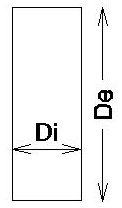
Simple hole. Di = the hole diameter. De = the hole depth. In this figure, the Draft Angle = 0.
- Counterbore — The part of the hole adjacent to the face is drilled with a larger diameter. This allows bolt or screw heads to be flush with or below the feature-based solid’s surface.
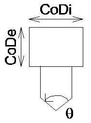
Counterbore. CoDe = Counterbore Depth. CoDi = Counterbore Diameter. = Drill Angle.
- Countersink — The part of the hole adjacent to the face is chamfered to allow bolt or screw heads to be flush with or below the feature-based solid’s surface.
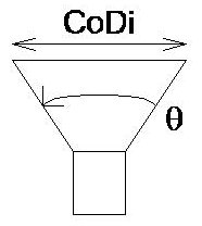
Countersink. CoDi = Countersink Diameter. = Csink Angle.
|
| Drill |
Sets whether or not a hole is drilled through a feature-based solid.
- Through — The hole passes through all faces of the solid.
- Blind — The hole passes through the solid until it reaches the specified depth. The hole may pass any number of faces to reach the required depth.
- Next Face — The hole passes through the solid until it finds the next face.
|
| Direction |
Sets the hole's direction.
- Face Normal — The hole is perpendicular to the selected face.
- Screen X, Y, or Z —
- Design X, Y, or Z —
- ACS X, Y, or Z — (If there is an active Auxiliary Coordinate System).
|
| Diameter |
Set the hole's diameter. |
| Depth |
(Drill > Blind only) Sets the depth a hole is drilled. |
| Draft Angle |
Sets the angle of the sides of the hole relative to orthogonal. A value of 0 means that sides of the hole are orthogonal to the identified face. |
| Drill Angle |
(Drill > Blind only) If on, sets the drill point angle. The default is 118 degrees. |
| Add Thread |
When selected, makes threaded hole options visible. |
| Cbore. End |
(Drill > Next Face or Through only) Defines which end of the hole has a counterbore.
- First Face — The end at the selected face has the counterbore.
- Last Face — The end at the face opposite the selected face has the counterbore.
- Both — Both ends of the hole have a counterbore.
|
| Cbore. Diameter |
Sets the diameter for the counterbore hole. |
| Cbore. Depth |
Sets the depth of the counterbore. |
| Csink. End |
(Drill > Next Face or Through only) Sets which end of the hole has a countersink.
- First Face — The end at the selected face has the countersink.
- Last Face — The end at the face opposite the selected face has the countersink.
- Both — Both ends of the hole have a countersink.
|
| Csink. Diameter |
Sets the diameter for the countersink hole. |
| Csink. Angle |
Sets the countersink's included angle. |
| Thread Diam. |
Sets the thread diameter. |
| Thread Depth |
Sets the thread depth. |
| Thread Pitch |
Sets the thread pitch. |
| Equation icons |
Lets you assign variables or equations to the corresponding setting. For more information, see Variables and Equations.
|