MicroStation CONNECT Edition Help

Constrain Elements


Used to apply tangent, perpendicular, parallel, or fix angle constraints to profile geometry.


SettingDescription
Method

Sets the method by which to constrain profile geometry.

  • Smart Constrain Elements — Constrains constructions tangent, perpendicular, or parallel, or by fixing the angle, depending upon the identified element(s) and the number of data points. This method is recommended unless you need to override or force constraints.

    LEGACY CONSTRAIN SMART
  • Constrain Two Constructions to be Tangent — Constrains two constructions (two circles, two ellipses, a circle or ellipse and a line) to be tangent at as many points as their geometry makes possible.

    LEGACY CONSTRAIN TANGENT
  • Constrain Two Lines to be Perpendicular — Constrains two lines (or the primary axes of two ellipses) to be at a right angle (90°) to one another.

    LEGACY CONSTRAIN PERPENDICULAR
  • Constrain Two Lines to be Parallel — Constrains two lines (or the primary axes of two ellipses) to the same rotation angle.

    LEGACY CONSTRAIN PARALLEL
  • Fix Angle of Line or Ellipse — Constrains a line's orientation or an ellipse's rotation angle.

    LEGACY CONSTRAIN ANGLE
Fix Angle Snap Tolerance

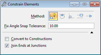
(Method set to Smart Constrain Elements only) Sets the tolerance for constraining a line or the primary axes of an ellipse (that is on an angle) to the closest view axis (x- or y-).

Used in conjunction with the Smart Constrain Elements method, this setting forces individually selected elements to be constrained to the view x- or y-axis if the current position of the element is within the tolerance value from a vertical or horizontal position.

For example, if Fix Angle Snap Tolerance is 10° and a single line drawn at 45° is identified, the line is fixed at 45°. If the line was placed at a 5° slope off the view x-axis, the line is forced to be horizontal.

This setting also forces multiple elements to be constrained parallel, perpendicular, or tangent with one another along the view x- and y- axes if the current position of the elements are within the tolerance value from a vertical or horizontal position.

Angle Lock

(Method set to Fix Angle of Line or Ellipse only) Constrains a line or the primary axes of an ellipse by the following options.

  • None — Geometry is constrained at the angle it was created.

  • Horizontal — Geometry is constrained to the view x-axis.

  • Vertical — Geometry is constrained to the view y-axis.

Settings

Toggles the display of the Convert to Constructions and Join Ends at Junctions check boxes.

Convert to Constructions

Converts primary elements to construction elements.

Join Ends at Junctions

Extends primary elements to intersection.

Key-in: LEGACY CONSTRAIN ELEMENT