| Shading Rate |
Controls the per material antialiasing value that represents the subdivision of a pixel, in the X and Y directions, for extra sampling values. For example:
- Setting the value to 1 means no subdivision is performed and one sample is taken per pixel.
- Setting the value to 0.5 means divide the pixel in half, in the X and Y directions, and take a sample for each new area. This results in 4 samples being taken for each pixel.
|
| Direct Illumination Multiplier |
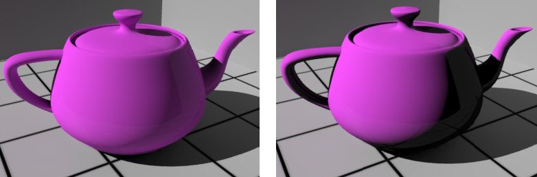
Controls the effect of direct lighting on the material. This setting along with Indirect Illumination Multiplier and Indirect Illumination Saturation are used for balancing the effect of direct and indirect illumination in the scene. In the following examples, the scene is illuminated with a Solar light only. For the image on the:
- Left – the teapot material has Direct Illumination Multiplier set to 100% (normal).
- Right – the teapot material has Direct Illumination Multiplier set to 0%. That is, no direct light is affecting the teapot and it is illuminated only by the light reflected from the walls and floor.
|
| Indirect Illumination Multiplier |
Controls the effect of indirect lighting on the material. In the following examples, the scene is illuminated with a Solar light only. For the image on the:
- Left – Indirect Illumination Multiplier is set to 100%. Areas that are in shade from the Solar light, still receive indirect illumination.
- Right – Indirect Illumination Multiplier is set to 0%. Areas that are in shade from the Solar light appear very dark.
|
| Indirect Illumination Saturation |
Controls the saturation of a material from the color of indirect light sources. In the following images, the Indirect Illumination Saturation setting for the teapot material in the image on the:
- Left - 100%, which is shown by the color of the indirect light affecting the teapot material.
- Right - 0%, which shows in the color of the teapot not being affected.
|
| Indirect Illumination Type |
Controls the type of indirect illumination algorithm used when rendering an element having the material. Choices are: None, Monte Carlo, or Irradiance Caching. In the following images, illumination is from an indirect light source (a light probe), and Indirect Illumination Type is set as indicated.
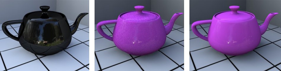
Left to Right, Indirect Illumination Type set to None, Monte Carlo, Irradiance Caching
When Indirect Illumination Type is set to None, the teapot is not illuminated. When set to the Monte Carlo algorithm, the result is more grain on the material than when Irradiance Caching is selected.
Where you have graining, you can reduce it by increasing the number of indirect rays.
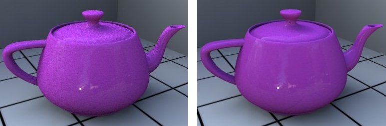
Indirect Rays set to 128 (left) and 1024 (right)
|
| Back Face Culling |
Determines whether a polygon of a graphical object is visible and verifies whether the points in the polygon appear in clockwise or counterclockwise order when projected onto the screen. The process makes rendering objects quicker by reducing the number of polygons for the program to draw. For example, in a city street scene, there is no need to draw the polygons on the sides of the buildings facing away from the camera; they are completely occluded by the sides facing the camera. Options are:
- Use Geometry Default
- Force Single Sided
- Force Double Sided
|
| Rounded Edge Width (mm) |
Adjusts the rendered result of surface normals at a polygons edge to blend them with adjoining polygon normals, giving the impression of a small rounded edge between the two intersecting faces. Note: It is merely a shading trick and will not round the edges of the actual geometry, nor change the objects silhouette in the rendered image. It shades polygons edges at render time to look as if a small rounded bevel has been applied, to what normally would be a sharp intersection. So it is best to set the width to just a few millimeters in the final rendered image.
|
| Casts Shadows |
If enabled, the material can cast shadows. If disabled, no shadows are cast by the material.
|
| Receive Shadows |
Controls whether or not the material receives a shadow from other objects in the scene.
Floor material with Receive Shadows on (left) and off (right)
|
| Visible to Eye |
Controls visibility of the material that is in the line of site of the eye in the scene. That is, whether or not geometry with the material will be rendered. If disabled, any geometry with the material applied will be invisible to the "eye" in the rendered image. The geometry still participates in the lighting calculations and can cast shadows into the view, but the geometry itself will not be directly visible. It still may be visible in reflections and refractions. Useful, for example, to remove an object (such as a tree) that is obscuring the item of interest.
In the following images, the material for the teapot has Visible to Eye enabled in the left image and disabled in the right image. Notice that in the right image the teapot material still casts shadows and is visible in the reflection, though the teapot is not visible.
|
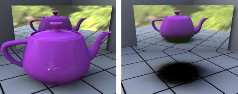
| Visible to Indirect Rays |
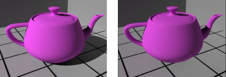
Controls visibility of the material during the indirect illumination pass. If disabled, those elements using the material do not contribute to the indirect illumination of the scene. In the following images, illumination is from a Light Probe, which is an indirect light source. The teapot material has Visible to Indirect Rays enabled in the left image, and there is a shadow under the teapot. In the right image, the setting is disabled and there is no shadowing from the teapot.
|
| Visible to Refraction Rays |
Controls visibility of the material in refractions. In the following example images, there is a block of glass in front of the teapot, covering the right half of it. The teapot material has Visible to Refraction Rays enabled in the left image and disabled in the right image.
|
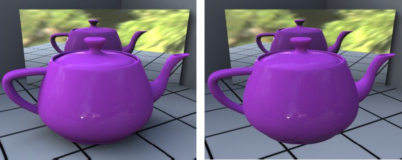
| Visible to Reflection Rays |
Controls visibility of the material in reflections. In the following example images, the teapot material has Visible to Reflection Rays enabled in the left image and disabled in the right image.
|
| Visible to Occlusion Rays |
Controls visibility of the material in ambient occlusions. If disabled, elements controlled by the shader will be invisible to occlusion rays calculations.
In the following images, the material for the teapot has Visible to Occlusion Rays enabled in the left image and disabled in the right image. Notice that in the right image, the teapot material actually does not retain any rays, and is visible only due to the shadows casted by the other teapot.
|
| Cut Material |
Allows a different material to be displayed when geometry associated with a material is cut by a clip volume. The drop-down menu lists the available cut materials. Cut materials can also use geometry maps, so they can display geometry maps in hidden line display mode |