To Create a Surface by Lofting Section Elements
-
Select the Loft Surface tool (
).

- To create a parametric surface, turn on Parametric.
- Select the first section element.
- Select the second section element.
- (Optional) Use <ctrl+data point> to select further section elements or hold down the Data button and drag a line to select the profiles. Pressing the <Alt >key changes the selection to a rectangle.
- Enter a data point to view the surface.
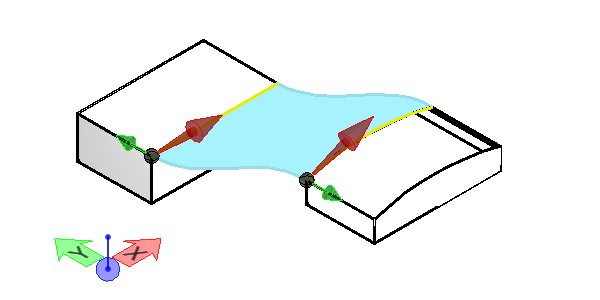
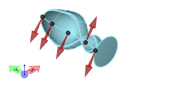
- (Optional) Modify the profiles. With closed profiles the direction of the red arrow can be changed and the location can be moved by dragging the rotation ball.
-
Enter a data point to accept the surface.
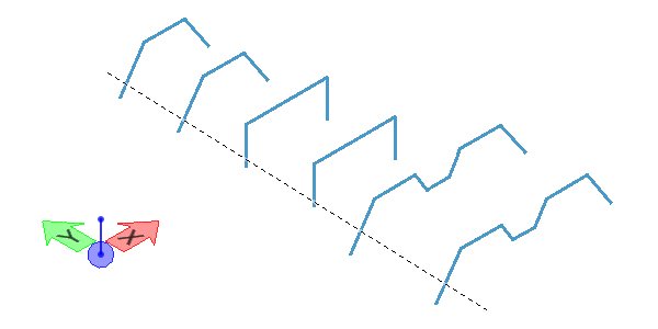
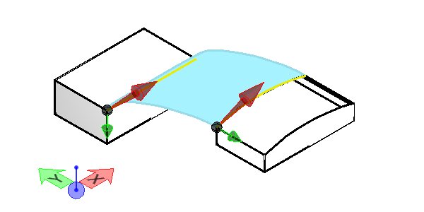
The Data button is depressed and a selection line is used to select the profiles. Force Start Point at Selection Point is on so that the endpoint of the curve closest to the selection line is used.
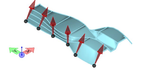
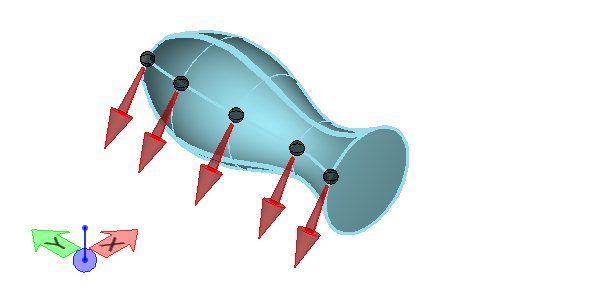
During the preview state, the red arrows can be adjusted. With open profiles, the direction of the arrow can be changed. Generally, the preview displays what will be generated. If the preview does not display, then the arrows need to be adjusted.
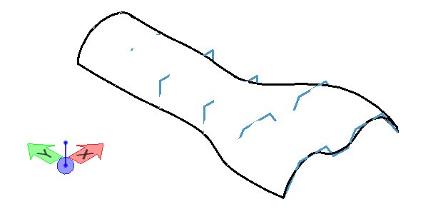
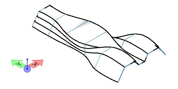
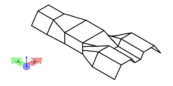
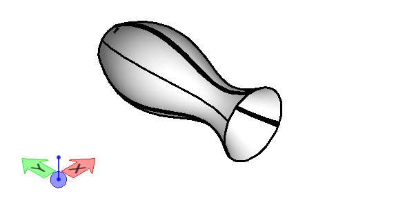
With Rebuild Profile Curves on, each section element is approximated by a B-spline curve, with the resulting surface being smoother. The dark blue profile curves show the difference between the original definition.
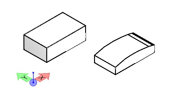
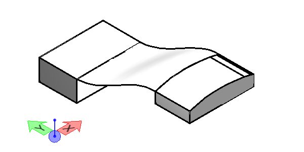
A loft can be made between two surfaces or solids or a combination of a starting solid or surface and a system of curves between. In this example two solids are used to loft between two edges.