To Create a Stroke Pattern Component (by Adapting an Existing Component)
-
In the Components list box, select the stroke pattern component to adapt.
The controls for working with stroke patterns are displayed.
-
From the Edit menu, choose Duplicate.
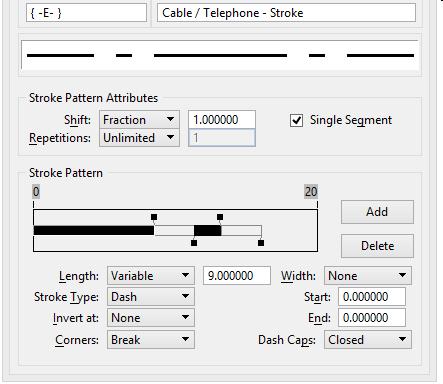
The component is duplicated. The duplicate is automatically selected in the Components list box, and a sample line with the stroke pattern component and the Stroke Pattern itself are displayed.
- (Optional) For each stroke you want to delete from the duplicate, select the stroke, and click the Delete button. To select a stroke, click the stroke in the Stroke Pattern display. The selected stroke is highlighted.
- (Optional)
For each stroke you want to add, click Add.
Each stroke is added to the (right) end of the Stroke Pattern as a gap stroke, which is indicated with an unfilled bar.
- (Optional)
For each stroke you want to change from a gap stroke to a dash stroke, select the stroke and choose Dash from the Stroke Type option menu.
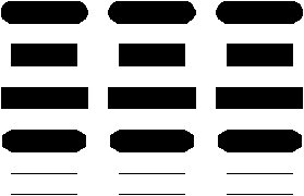
Each dash stroke is indicated with a filled bar. The resulting stroke pattern component is displayed above the stroke pattern display.
- (Optional)
Set other stroke attributes.
To permit the length of the selected stroke to be adjusted when the stroke pattern is fractionally shifted or repeated a fixed number of times, choose Variable from the Length option menu. Otherwise, choose Fixed.
To change the length of the selected stroke, key in the length, in master units, in the Length field. You can also change the length of a stroke by dragging its handle, which is located in the Stroke Pattern display above or below the ending point of the stroke.
To set the type of end cap to be displayed on the selected stroke when the stroke is displayed with width, choose the desired end cap type from the Dash Caps option menu.
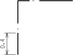
To cause the selected stroke to break at element vertices, choose Break from the Corners option menu. Otherwise, choose Bypass.
To display the selected stroke with width, choose Full from the Width option menu.
or
To cause only the left or right half of the stroke to be displayed (with width), choose Left or Right from the Width option menu.
or
To display the stroke without width, choose None from the Width option menu.
If the selected stroke is a dash stroke that is set to display with width, to set the stroke's start and end width, key in the widths, in master units, in the Start and End fields. To taper the stroke, set Start and End to different values.
- (Optional)
Set stroke pattern attributes.
To set the fraction of the first stroke that is displayed at the start and end of an element (or element segment) displayed using this stroke pattern, choose Fraction from the Shift option menu and key in the desired fraction, in decimal, in the field.
To set the distance, in master units, that the stroke pattern is shifted relative to the beginning of an element (or element segment), choose Distance from the Shift option menu, and key in the desired distance, in master units, in the field.
To set the number of repetitions of the stroke pattern along the length of an element (or each segment), choose Count from the Repetitions option menu and key in the desired number in the field.
To cause the stroke pattern to repeat continuously along the length of an element (or each segment), choose Unlimited from the Repetitions option menu.
To truncate and restart the stroke pattern for each element segment (displayable vector), turn on Single Segment.
To continue the stroke pattern across element segments, turn off Single Segment.
- (Optional) In the field below the Components list box, key in the component description.
- From the File menu in the Line Style Editor dialog, choose Save.