Using Drawing Models
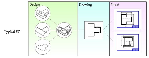
The basic concept of drawing models is that a "subject" is composed from many different designs into a single design composition.
One example subject to use is a house. If you have separate files for the floor, roof, and walls, you can have three people work on them simultaneously. To do this, you reference in complimentary information as you need it. In this example the person working on walls would want to reference in the floor. When there is enough floor to make his decisions, he can start placing walls. The person working on the roof may be more interested in the walls than the floor. He may even turn off the reference to the floor file.
There is a logical sequence to the house subject because you design the floor, then the walls, then the roof. However, the roof affects the walls and the floor when it is further along. When the roof is designed, it's the weight needs to be engineered, so walls may need to be upsized or moved, and the floor may need to change to support the desired clearances and space. The models interact and influence each other as they become more populated.
What does this have to do with the single reference in the drawing model? While it is perfectly fine to reference complimentary information into the drawing model, this information is not part of a centralized model and will not show up in other drawings. Let us say that someone has a 3D model of a site that shows the lay of the land where our little house is located, and let us say we created a floor plan drawing model. If we reference a top view of the site into our floor plan drawing model, that is not a best practice.
Why? If you create a section in that floor plan drawing model, you will see only the house or the site, but not both composed together. This is because they are still in separate worlds. You could move the site reference wherever you want in the 2D drawing, rotate it to the wrong location and scale it. You do not even know if the site is at the correct elevation; you just see the 2D top view of it.
The recommended way to do this is to reference the site, floor, walls, and roof into a 3D design composition so there is one source of truth and the designs are composed correctly. By creating views in this design composition, you have centralized the control of what you see. You also can create more design compositions if desired.
In a drawing model, the reference is attached at a 1:1 scale. Due to this, making changes to your model is easier in the drawing model than in the sheet model.
When a 3D design model is directly referenced to a drawing model, you can set the visible edges display of the reference to Cached. The Cached Visible Edges option stores the edges for a drawing or sheet attachment in an intelligent cache that associates the edges with their underlying geometry. When an attachment is set to Cached, it performs a snapshot of the geometry when the cache was generated. The cached visible edges display will not change to reflect model changes until the cache is reloaded.
Properties of a Drawing Model
Some of the important properties of a drawing model are:
- A drawing model is always 2D.
- It does not have a sheet boundary.
- The default background color of a drawing model is gray.
- A reference attached to a drawing model is 1:1 coincident.
- Drawing boundaries should not be placed in a drawing model because their fields cannot be updated.
- Annotations can be placed in a drawing model.
- A drawing model supports harvesting.
- Clipping and full support for display styles.
- Ability to pre-specify the detail scale of a drawing model. When a drawing model is attached to a sheet, the drawing model's annotation scale is used as the attachment's default detail scale.
- Each drawing model should contain only one attached saved view. The drawing model acts a container for annotations specific to that saved view. If you want to place more than one saved views on a sheet, you should create a separate drawing model for each saved view.