To Add Distance Constraints to a Rectangular Cut
- Select the Constrain Feature tool.
- Click the Add New Constraints icon and the Distance icon.
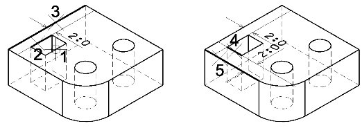
- Select the Distance check box and in its field, type 2.0.
- Select the rectangular cut feature in the solid.
- Select an edge of the feature to be constrained.
-
Select the edge on the solid to which the constraint will be referenced.
The constraint dimension displays dynamically.
- Using <ctrl+data point>, select the second edge of the feature to be constrained.
-
Using <ctrl+data point>, select the edge on the solid to which the constraint will be referenced.
The constraints dimension displays dynamically.
-
Accept to preview the effect of the constraints.
The cut is repositioned to the location defined by the constraints.
- Accept to complete the constraint.


Finally, an equation will be used to constrain the remaining hole to be clear of the edges of the solid by 1.5 times the diameter of the hole. Because there are two holes in this solid, first it must be established which hole is being constrained. For this, Feature Manager can be used. This lists all the features of the solid, with unique numbers (node numbers). As well, any features that are alrady constrained will have an asterisk (*) next to them in Feature Manager.