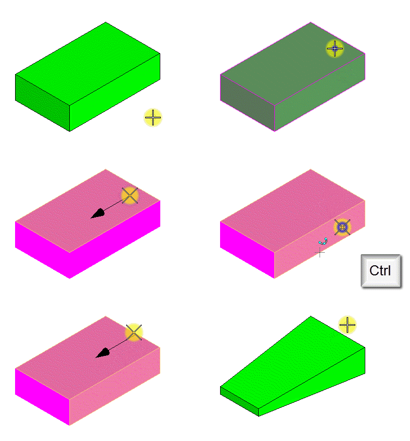
To Taper a Face(s) of a Solid
-
Select the
Taper Face tool.

- Select the Direction from the menu.
-
In the
Draft Angle field, type the required angle for
the taper, or use
Variable link
 to set it from the
available variables in the
Variables dialog.
- If required, turn on Add Smooth Faces.
-
Select the solid.
The solid is highlighted.
-
Select the face to taper.
The selected face is highlighted. This also defines the vector start point for the taper.
- (Optional) Select additional faces using <ctrl+data points>. That is, press <Ctrl> and move the pointer until the required face is highlighted. While holding down the <Ctrl> key, enter a data point to select the highlighted face. You can reset to deselect the last selected incorrect face.
-
Enter a data point to define the vector end point for the taper.
The vector start and end points define the direction of the taper, onto which the draft angle is applied. On defining the vector end point, the taper is constructed.


