Examples of Display Rules
The following examples explain how display rules work. Let's say you have a design of an office, as shown below.
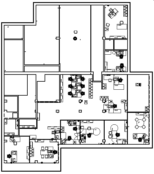
Example 1 - You want to identify all the rooms in the office that have an area greater than 30 square meters and display their boundary in blue color. To achieve this, you will create a display rule set with a display rule having following condition and action:
Condition - Create the following condition in the Condition Editor dialog.
ELEMENT.Shapes.Area > 30.000M2
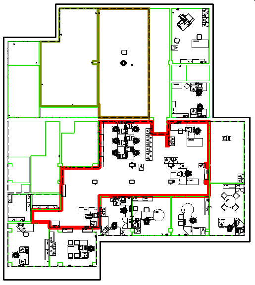
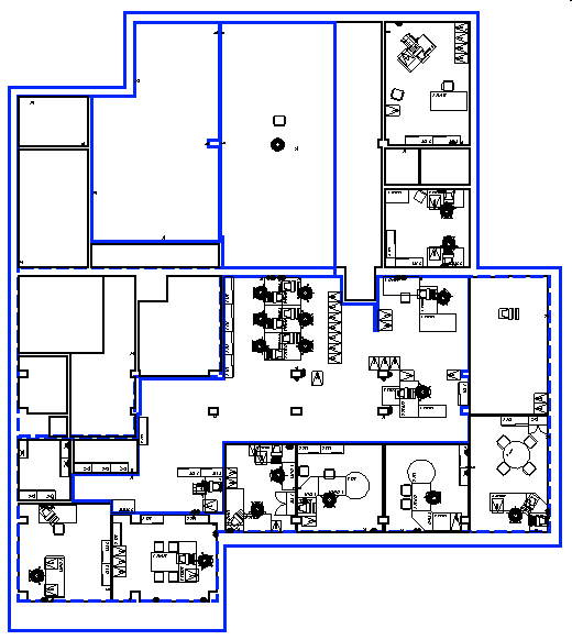
Assigning the display rule set to the display style and then assigning the display style to the view displays the following:
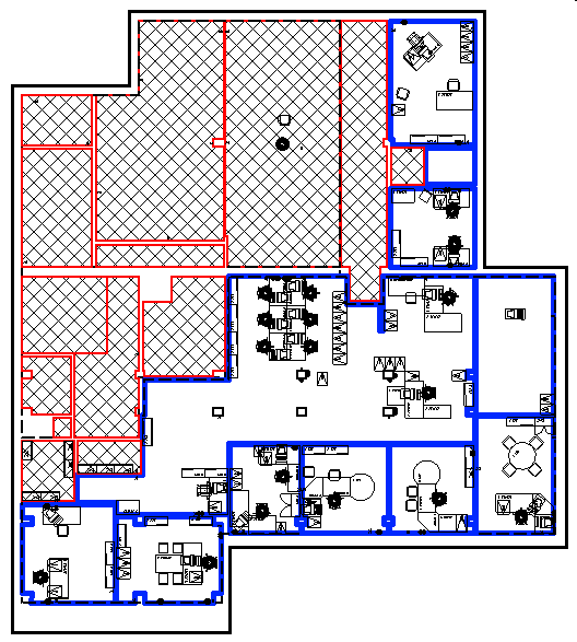
Example 2 - You want to identify the rooms that are occupied and that are unoccupied. The occupied rooms should be displayed in a thick blue boundary and the unoccupied rooms should be displayed as crosshatched areas with room boundaries in red . Let's assume you have an item called Room that has a property called Occupied. The status of the Occupied property identifies whether the room is available. To identify the occupied and unoccupied rooms, you will create a display rule set with two display rules, each having following conditions and actions:
Display rule 1 - For occupied rooms:
- Condition - To identify the occupied rooms you will set the following condition.
ELEMENT.Room.Occupied = Yes
- Actions - Set the following actions to the occupied rooms:
- Turn on the Symbology Overrides setting.
- Turn on the Enable/disable element color override check box. Click the drop-down list next to the check box and select blue color from the Active Color dialog.
- Turn on the Enable/disable line weight override check box. Select the desired line weight override from the drop-down list next to the check box.
Display Rule 2 - For unoccupied rooms:
- Condition - To identify the unoccupied rooms you will set the following condition.
ELEMENT.Room.Occupied = No
- Actions - Set the following actions in the Display Rules dialog:
- Turn on the Hatch Area setting.
- Select the Hatch Area icon and in the hatch area settings window turn on the Crosshatch Area check box.
- Turn on Symbology Overrides setting.
- Turn on the Enable/disable element color override check box. Click the drop-down list next to the check box and select red color from the Active Color dialog.
Assigning the display rule set to the display style and then assigning the display style to the view displays the following:
- In the Display Rules dialog, select Generate.

The Generate Display Rules dialog opens.
- In the Generate display Rules dialog, make the following settings:
- From the Property drop-drown list, select the property Room.Net.area.
- Set Method to By Range.
- Set Rules to 8.
- Turn on the Enable/Disable element color override check box.
- Turn on the Enable/Disable line weight override check box. In the drop-down lists next to the check box set the minimum line weight to 0 and maximum line weight to 7.
- In the Preview section, check the display rules that will be generated.
- Click Generate.
The Display rules are generated and displayed in the Display rules dialog.
Assigning the display rule set to the display style and then assigning the display style to the view displays the following: