Exercise: Creating a
Generated Node Type from the Crossbar
Select the
(Generate Node Type)
tool from the Node Types ribbon toolbar.
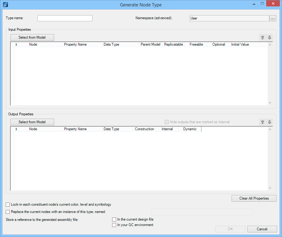
The Generate Node Type dialog opens.
Click
Select from Model.
This enables you to select geometry from the model as
inputs to the generated node.
In the Status bar, you are prompted to
identify an element, and the Graph nodes turn grey to prepare for the
selection.
Select the crossbar polygon (polygon2).
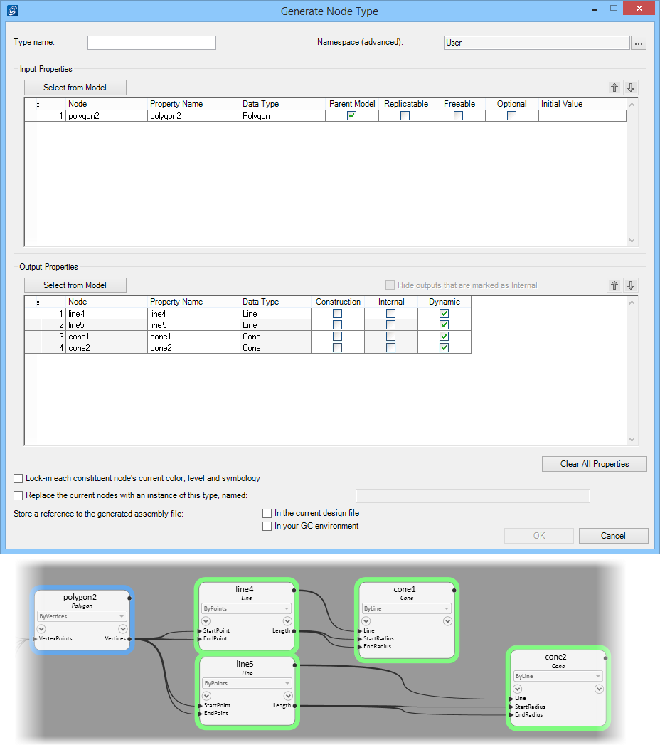
The Generate Node Type dialog is populated with
Input Properties and
Output Properties derived from
polygon2. Polygon2 is the input and the lines and
cones (line4, line5, cone1 and
cone2) are the outputs. In the Graph, the input and
outputs are color coded. The input (polygon2) is blue
and the outputs (line4, line5, cone1 and cone2) are green.
In the
Input Properties table, on row 1 check
Replicatable.
This enables you to use multiple shapes as inputs,
not just one.
In the
Output Properties table, on rows 1 and 2,
check
Construction for the two diagonal lines (line4
and line5).
This will hide these construction lines in the final
placed crossbar node.
Check the
In your GC environment option for the
Store a reference to the generated assembly
file: setting.
This will allow you to use the generated node in
future sessions.
Enter
crossbar1 in the
Type name: field.
Adding a number to the name is good practice as you
are likely to create several versions of the node and will need to distinguish
them in the nodes list.
Entering a name enables the
OK button.
Click
OK.
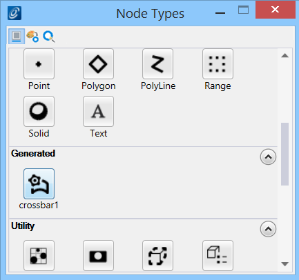
The Generate Node Types dialog closes, and the
new node type
crossbar1 is added to the Node Types dialog in the
Generated category.
 (Generate Node Type)
tool from the Node Types ribbon toolbar.
The Generate Node Type dialog opens.
(Generate Node Type)
tool from the Node Types ribbon toolbar.
The Generate Node Type dialog opens.