Exercise: Creating the geometry of a Crossbar
Next create a
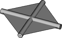
simple crossbar panel. You will use a placeholder shape to create it. You will
then create a new node from it. Afterwards you can use the new node to populate
the roof surface using the grid of shapes instead of the placeholder as the
input to the crossbar panel. This will create an elegant lattice as a roof,
which still can be manipulated moving the initial four points of the path.
-
Note: In order to create a crossbar feature you first have to create a placeholder to simulate the roof input point grid.Click the
 (Point) tool in the
Place Geometry ribbon toolbar.
Place four planar points in a square configuration away from
the roof.
(Point) tool in the
Place Geometry ribbon toolbar.
Place four planar points in a square configuration away from
the roof.
-
In the Node Types dialog select the Polygon node.
Polygon2 is added to the
Graph. Make sure its technique is set to
ByVertices.
The VertexPoints required input needs to be in the form of a list of points.
- Click on the VertexPoints required input to access its expression field. Place the cursor in the expression field, press and hold <Ctrl>, and select the four points you created earlier. The expression {point6, point7, point8, point9} is generated. Click away from the Polygon2 node to close the expression field and apply the expression. Polygon2 is added to the model. In the Graph, wires are drawn from the VertexPoints input to the four points' overall nodes.
- In the Graph create a selection set of the four points used to define Polygon2. Right-click and select Visible. This is important because to be able to replicate the Generated Node Type (a generative component) using a polygon grid you need to use only the polygon vertices as inputs, not the underlying points. The Visible option toggles the visibility of the selected points in the model view to off. In the Graph, the selected point nodes are greyed out indicating their display is toggled off.
-
Create the crossbar members by first creating a diagonal line in
each direction.
- In the Node Types dialog select the Line node. Line04 is added to the Graph. Make sure its technique is set to ByPoints.
- Enter polygon2.Vertices[0] in the StartPoint input expression field.
- Enter polygon2.Vertices[2] in the EndPoint input expression field.
- In the Graph, select line04, right-click and select Copy. Right-click in the Graph away from any nodes and select Paste Node(s). A new node line5 is added to the Grid. It is an exact copy of line4.
- Edit Line5's StartPoint input by entering polygon2.Vertices[1] in its expression field.
- Edit Line5's EndPoint input by entering polygon2.Vertices[3] in its expression field.
- In the Node Types dialog select the Cone node. Node cone1 is added to the Graph. Make sure its technique is set to ByLine.
-
Define
cone1's required inputs.
- Draw a wire from the Line input to line4's (one of the diagonals) overall node.
- Enter line4.Length/25.0 in the StartRadius and EndRadius required input expression fields. As the starting and ending radii, you would not want a fixed number as the scale of the generative component is not fixed. In order to make it responsive you need to tie the radii proportionally to the length of the diagonal. 25.0 is an arbitrary scaling factor to scale down the radii, feel free to adjust it.
- In the Graph, select cone1, right-click and select Copy. Right-click in the Graph away from any nodes and select Paste Node(s). A new node cone2 is added to the Grid. It is an exact copy of cone1 including wires linking it to other nodes.
-
Right click on the wire connecting
cone2's Line input to
line4's overall node and select
Disconnect This Wire from line4.
The wire becomes detached from
line4 and its endpoint is attached to the
pointer. The wire is displayed with a blue dashed line. Connect the wire to
line5's overall node.
The wire becomes attached to
line5 and changes to a s7olid black line.
Tip: You were able to re-rout the wire because you selected it closer to the line4 node than the cone2 node (in the Graph). If you selected it closer to the cone2 node, the option Disconnect This Wire from line4 would not be available. Rather, the option Delete This Wire would be available and appropriate for this edit. You would have to draw a new wire instead of re-routing the existing one.
- Edit cone2's StartRadius and EndRadius required inputs with the expression line5.Length/25.0.
- Record User Changes into Transaction file.