Grid Node
 (Grid
node) is integrated with the
AECOsim Building Designer Grid System. Its default
technique,
OrthogonalGrid allows you to select from the
Grid design you create using the Grid System. Other techniques —ByGrid, or
RadialGrid can be set, as required.
(Grid
node) is integrated with the
AECOsim Building Designer Grid System. Its default
technique,
OrthogonalGrid allows you to select from the
Grid design you create using the Grid System. Other techniques —ByGrid, or
RadialGrid can be set, as required.
- Add a Grid node to the Graph. The default OrthogonalGrid technique is active.
- Select the ByGrid technique, for example to study the parameters of the active grid system. The grid node uses the values from active floor and building currently set in the Floor Selector.
- Click next to the GridName port. The expression field becomes a drop menu listing Grid definitions existing in your active project. Select an existing grid name (ProjectGrid). The Node properties list the default grid system parameters.
- Use Node Properties dialog to alter the grid node properties, if required to override the default values.
- Click Synchronize to append the grid parameters of active Grid System.
- Set Auto to automatically synchronizes and writes grid parameters.
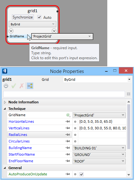
The input ports vary for techniques other than ByGrid; for example, for OrthogonalGrid technique, the input ports —Horizontal / Vertical Lines, Building Name, and the Start and End Floor names are required. Similarly, for RadialGrid, in place of horizontal/vertical lines, the Radial and Circular Lines ports are needed.