Utilities Conflicts
The Clash Detection tool allows you to identify sets of elements to be used for the detection of physical clashes and clearance problems between the elements.
Detected clashes are stored as conflict nodes in the DGN model. These nodes can be queried and reported on like other node types using the reporting tools available in the Drainage and Utilities toolset, such as flex tables
Interface
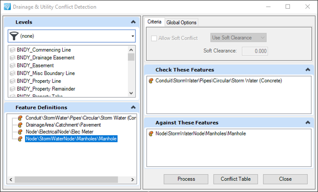
The Conflict Table button opens the Conflict FlexTable.
Criteria
You can set up of the features which get checked for clashes against other features. For example, as shown above all feature with Feature Definition of Gas Line will get checked against all Feature Definitions of Water Line.
You can define Feature Definitions, as shown above, or levels by dragging the definitions from left side into either the Check or Against portions of the dialog on right.
You can check features against themselves (for self clashes, or clashes between features sharing the same feature definition) by placing the Feature Definition in both the Check and Against sections.
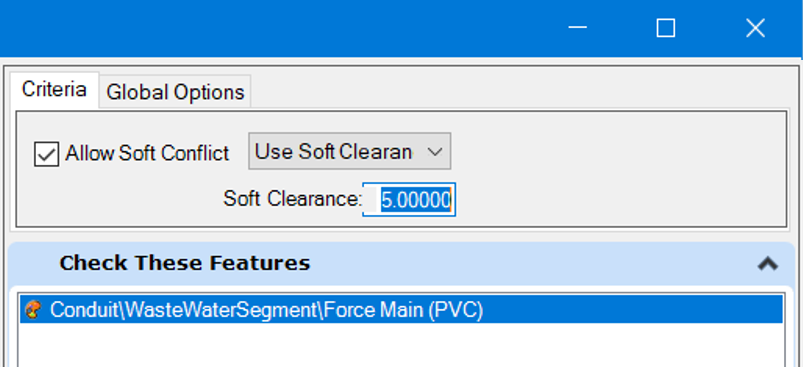
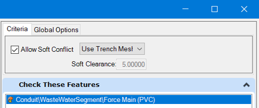
Allow Soft Clash
You can define soft clash parameters for each entry independently. Select one or more of the Check or Against entries and toggle on the Allow Soft Clash toggle.
When defining soft clashes, you can define an envelope around the feature by setting the option to soft clash.
Or you can use any trench associated with the feature by setting the soft clash option to Trench.
Global Options

Merge Tolerance – Any multiple detected clashes found within this tolerance distance will be combined and represented as a single clash.
Surface – Allows choosing a terrain model which is found in the model to define top elevations of conflict nodes. Ellipses can be used to select the existing terrain model in the dgn.
Feature Definition – Allows defining a Feature Definition to be assigned to the conflict nodes.
Conflict Nodes

Presentation
Conflict nodes presentation are determined by Feature Definitions. In the absence of a feature definition, they are shown generically as a cube in 3D and a half filled circle in plan model.
Properties

Feature Name – the name of the node.
Feature Definition – the assigned Feature Definition.
X, Y, Z – coordinate of the node location.
Station (Start and End) – a conflict node may be configured as an area of interest by change these to define a length along the conflicted element.
Offset (left and right) – a conflict node can be configured as an area of interest by changing these to non-zero.
Feature B – the feature which was used as the Check element in clash detection.
Feature A – the feature which conflicts on the conflicterr.
Responsible Party – A user defined field which allows tracking of person responsible for determining resolution of the conflict.
Current Status – allows tracking of the current state of conflict resolution.
Requires test hole – allows cataloging of which conflicts need further investigation by test hole field exploration.
Recommended Resolution – allows cataloging the recommended action to resolve the conflict.
Conflict type – Hard (a physical clash between the two features) or Soft (a clearance clash).
Differences from MicroStation Clash Detection