Place Nodes
 Used to either create nodes of
any type that are equally spaced along a linear element, or to create catch
basins that are spaced according to spread width constraints.
Used to either create nodes of
any type that are equally spaced along a linear element, or to create catch
basins that are spaced according to spread width constraints.
Set the Spacing Method, depending on your requirements:
- "Interval" lets you place nodes of any kind - Stormwater, Electrical, etc. The nodes can be linked with conduits. The nodes are placed at a constant interval, measured along a selected linear element.
- "Spread" only lets you place catch basins that use an Inlet Catalog, with an Inlet Type of Combination, Curb, or Grate, and Catchments. The catch basins can be linked with gutters. The catch basins are placed at the optimum positions along a selected linear element to collect runoff from the catchment, without exceeding the spread criteria.
Ribbon
Layout > Layout > Place Nodes
Workflow
Select Reference Element for Node Locations - Pick the element that you want to use to define the locations of the nodes. Nodes will be placed at equal distances along this element.
Interval Spacing Method
Interface for Interval Spacing Method

Node Location Reference - Select the element that you want to use to define the locations of the nodes. Nodes will be placed on the selected element at equal distances.
Vertical Offset - Define the offset from the elevation reference element. Enter a positive or negative value to place node above or below the elevation reference element.
Interval - Define the interval between the nodes.
Start Station - Define the start position on the reference element.
Stop Station - Define the stop position on the reference element.
Offset - Define the offset from the reference element. Enter a negative value to offset nodes to the left of the reference element.
Select Rotation or Reset to Place Again - The rotation value is relative to the selected linear element. This value is applied to the construction class, line style 3 lines in the cells that make up the 2D and 3D definition of the node.
Data Point to Accept Design - The locations of the nodes are shown in the graphics. Data point if they are what you want. A Reset will take you back to the previous step.
Feature Definition - Defines the feature definition to be assigned to the new nodes.
Name Prefix - The feature definition provides a default naming prefix, which can be overridden here.
Create Conduits - Check this box if you want to create conduits between the nodes.
Conduit Feature Definition - Define a feature definition to be assigned to the new conduits. The list of feature definitions is restricted to those of the same utility type as the nodes - e.g. Storm Water, or Communications.
Conduit Name Prefix - The feature definition provides a default naming prefix, which can be overridden here.
Description - A conduit feature definition can contain multiple definitions for size. The available sizes are listed here.
Note: Each of the nodes created by this tool are individually ruled to the reference element.
The properties for each node created by this tool will include a Point Constraints category, which will have properties for the station and offset. This is the same functionality as placing a single node using Civil AccuDraw > Station and Offset. Changing either constraint will update the selected node only.
Once the nodes have been placed, their properties, manipulators, and other functionality is the same as for a single node. See the Place Node topic for further information.
Spread Spacing Method
Prerequisites:
The current scenario must use Calculation Options that are set up to use the GVF-Rational Active Numerical Solver. This scenario also defines the Rainfall and Runoff Alternative, which provides the rainfall data that is used to calculate flow from the catchment areas.
The feature definition in the Feature category can only be for a catch basin, with a prototype which defines that it uses an Inlet Catalog. The selected item in the inlet catalog needs to be a Combination, Grate or Slot, as these types use HEC-22 calculations to determine capacity.
Recommendations:
It is recommended that the prototype does not use a Gutter Catalog. This is because doing so defines a single value for the Road Cross Slope. In practice, where a road has superelevation, the road cross slope will vary along the road, and you will therefore want the correct value to be used at each location where the spread width and depth are checked. The Place Nodes command will do this automatically (to ensure the most accurate results) regardless of whether the prototype uses a Gutter Catalog or not. However, when you subsequently compute a scenario, the road cross slope in the Gutter Catalog will be used if it has been set.
It is recommended that the Feature Definition for the gutter uses a prototype that is set up with a Gutter Type of Use Gutter Sections. Whilst not essential, this means that the spread width and depth will be calculated at intervals along the gutter. The calculations use the instantaneous road cross slope and longitudinal gradient from the terrain model, to ensure the most accurate results. This also gives you the best chance of identifying any anomalies in the road surface.
The linear element selected for the Node Location Reference should be a gutter flow line - in other words the linear which models where the road / shoulder / gutter meet the curb.
The terrain model selected for the Node Elevations should include all necessary linear elements to ensure that it accurately represents the road, shoulder, gutter and curb, and correctly reflects the application of superelevation. This will determine the area of the surface that flows to each catch basin.
If your road and terrain model includes accesses, such as driveways and intersections, then the linear element for the gutter flow line will contain a gap and there won't be a curb across the access. This will cause an issue, because the spread width calculations assume that there is a gutter and curb, and also because flow may (depending on how the surface slopes) run into the access, and never reach the curb on the downhill side. To cater for this situation, it's recommended to place a catch basin just before the start of the access, and select it by using a right-click when prompted for the end station. Similarly, if the slope of the access is such that it will contribute flow to the road under consideration, then place catch basins and catchments as required in the access, then select a location downhill from the access, or an existing catch basin, as the start station.
How it works:
Starting at the Start Station or existing node, the command works downhill along the Node Location Reference. At each location, a catchment is delineated from a terrain model, its flow is calculated, and this is used to check whether the spread width or depth is exceeded if a catch basin were to be placed at this position. If the spread width or depth have not been exceeded, then the catch basin is moved to the location (defined by the Step Distance) and the checks are performed again. This process repeats until either the spread width or depth have been exceeded, in which case the location of the previous step distance is used for the catch basin, or the Maximum Spacing has been exceeded.
Catch Basins don't often capture incoming flow with 100 percent efficiency. This command automatically assumes that any flow not captured by one catch basin will carryover to the next catch basin - regardless of whether gutters are being placed or not. If this assumption was not made, then the spacings between catch basins would be too large.
If the End Station is specified by selecting an existing catch basin, then a catchment will be delineated for that catch basin.
Interface for Spread Spacing Method
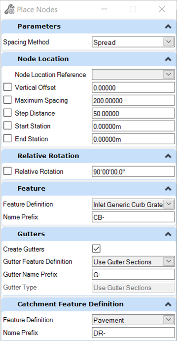
Node Location Reference - Select the linear element that you want to use to define the locations of the nodes.
Node Elevations - Select the terrain model element that you want to use to define the top elevation of the node, and to delineate catchments.
Vertical Offset - Define the offset from the elevation reference element. Enter a positive or negative value to place node above or below the elevation reference element.
Maximum Spacing - if the spread width or depth has not been exceeded when this distance is reached (either from the previous catch basin or the start station) then a catch basin will be placed here. Think of this as a "fail-safe" distance - designed to stop the distance between catch basins exceeding a reasonable limit for maintenance purposes.
Step Distance - this is the distance, measured along the Node Location Reference linear, at which a catch basin will be placed, and the spread width or depth checked.
Start Station - Define the start position on the reference element, or right-click to select an existing catch basin.
Stop Station - Define the stop position on the reference element, or right-click to select an existing catch basin.
Select Rotation or Reset to Place Again - The rotation value is relative to the selected linear element. This value is applied to the construction class, line style 3 lines in the cells that make up the 2D and 3D definition of the node.
Data Point to Accept Design - Data point to start the process. A Reset will take you back to the previous step.
Feature Definition - Defines the feature definition to be assigned to the new catch basins.
Create Gutters - Check this box if you want to create gutters between the nodes.
Catchment Feature Definition - Define a feature definition to be assigned to the new catchment areas.
