Extract Utilities From Graphics
The Extract Utilities from Graphics tool provides the ability to create utility models from graphic elements. These elements may result from survey processes, GIS graphic data, OpenRoads Geometry or other sources. But, in every case the elements are DGN graphic elements.
The following workflows are supported:
- Utilities are created in
batch – the most common situation for this workflow is where the graphics are
provided by Survey or GIS graphic data. This workflow will utilize user
definable and reusable filters to read graphic data and assign utilities en
masse.
- A special case of this workflow is the modeling of an existing drainage system. A drainage system when shown in graphics will consist of individual links which connect to nodes. Links will be shown in graphics as lines while the nodes will be a point (usually represented by cell) indicating the node type and, usually, top elevation. There may be an additional point to indicate the invert elevation of the node. By using preconfigured graphic filters the user can model the drainage network and connectivity. The most common use case here is that the nodes and links are created from survey of existing drainage features.
- Utilities are created By Selection Set – a common situation for this workflow will be used for design of individual utility lines such as relocations of portions of a line on a road/site project. The source data in this workflow will often be OpenRoads Geometry elements.
Notes
- The utilities require no other input other than the graphical elements and their symbology.
- No specific tool is required for collecting or preparing the graphics.
- No specific data coding or data collection methods are required, since only the end graphics are consumed.
- Any OpenRoads Surface (Terrain model, Mesh or Object) can be used to derive elevations.
- 3D graphic elements can define their own elevations without need for any surface.
- Drainage and Utilities Feature Definitions are used to define the resultant appearance of the physical model.
Interface
The command is structured to accommodate both workflows described above based on the method chosen in dialog or command prompts.
Selection Method
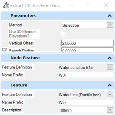
- When method is Selection
inputs are:
- Vertical Offset – Defines depth under selected surface by which to define the utility.
- Search Radius - If the end points of the graphics being extracted are within this value, then a single node is created, instead of multiple nodes.
- Node Feature - Assigns the feature definition to the resulting utility nodes. If the Element Template assigned to the Solid Feature Symbology includes cells, then they are used when the node is displayed in the 3D model. If cells are not assigned, then hard-coded graphics are used for the 3D model. The hard-coded graphics can be useful in some situations, such as when there is a junction of several lines for a utility feature such as water segments.
- Feature - Assigns the feature definition to the resulting utility conduits.
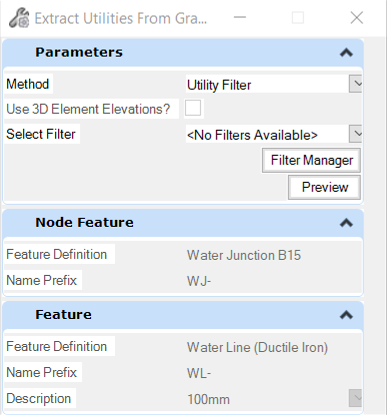
Graphic Filter Method