Properties
Ribbon: Home > Primary

In addition to the categories of information that you see for any selected Civil element, the properties of a drainage element also include a category called Drainage and Utilities. This contains some basic information on the selected element, such as elevations, slope, operational status and also lets you open the Utility Properties, to see more information.

If you have selected a node, then the Drainage and
Utilities category includes several other fields, as follows:
- Use Slope of Surface - Whether the top 3D cell should slope at the same slope as the surface or element that was used to define its top elevation. Normally set to True for catch basins and manholes, and false for headwalls.
- Elevation Reference - Shows the selected element (e.g. a terrain model) from which ground elevations are measured. Clear this field if you want to type in a ground elevation.
- Station/Offset Reference - Lets you select a linear element (e.g. a road centreline) to calculate the station and offset of the node relative to this element. Note that the resulting information is displayed in the Utility Properties, in a category called References, so that it can be included in FlexTables if required. This might be done if a FlexTable is being used to create Setting Out data for example.
- Elevation is the Invert - Lets you state that the elevation that is obtained from the Elevation Reference, or you type in when you place a node, is for the invert of the node - not the ground. In other words, you are defining the elevation of the hydraulic flow line of the node, which is defined by the construction class, line style 5 point. This only applies to cross-section, headwall, and outfall nodes, which use a single 3D cell.
- Match Slope of Conduit - Lets you state that the longitudinal slope along a node should match the slope of the conduit that it connects to, instead of being flat. This only applies to cross-section, headwall, and outfall nodes, which use a single 3D cell.
If you have selected a conduit, then the Drainage and
Utilities category includes one other field, as follows:
- Single Gradient - This is always set to true for storm and sanitary conduits. For other types of conduit, it is set in the Feature Definition. If true, the conduit has a single gradient from the start node to the stop node. If false, the conduit follows a reference surface (example, a terrain model) at a depth below it which is defined in the Conduit Table in the Feature Definition. You are prompted to select the surface when you place the conduit, after you select the start and stop nodes. This depth can be amended if needed, after the conduit has been placed. Set Single Gradient to False to amend the elevations of bend points in profile, and to use the Table Editor to amend the profile of the conduit.
Note that if you want to model a change of gradient in a storm or sanitary conduits, such as to model a syphon for example, then you should use the Insert Node tool to insert Transition nodes in the conduit, and choose to split the conduit in to two when you are prompted.
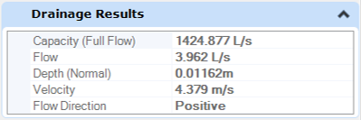
The properties of a drainage element also include a second category
called
Drainage Results. This contains some basic
information on the selected element, such as flow speed, direction of flow and
depth of flow.