Filter Manager
Creating Filter Groups with the Utility Filter Manager
The Manager can be accessed from within the Extract from Graphic tool or directly from the Filter Manager tool located in the Layout tool group. The general workflow for setting up filter groups is to create the individual filters for individual utility features, then combine them into a filter group. For example, perhaps a common dataset might consist of points and conduits using the levels points and conduits respectively. Create a filter for points and a filter for conduits, then combine into a filter group and assign a meaningful name so it's easy to tell its contents. Keep in mind you can use a filter group that has more filters than you have in your data. If no data is found for a particular filter, the filter is just ignored.
Create a Filter
- Select the Create a Filter from the icons at the top of the dialog or right-click on Graphical Filters and select Create a Filter. A line named "New Filter" is added to the hierarchy. You can rename this to something appropriate at any time.
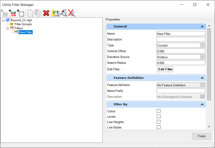
- Highlight the filter just created, and note the right pane of the dialog has the Properties pane with General and Filter By Sections.
General
Here you will specify how little or how much data to use in order to utilize when utilities are created. For example, it may be as simple as specifying a level. Or you may want to specify level, color, or other MicroStation attributes. Select enough information to make it a filter unique from other elements in the file.
|
Settings |
Description |
|
Name |
Brief, unique name to identify the filter. |
|
Description |
Optional description to further identify the filter (if the Name is insufficient). |
|
Feature Type |
Select the feature that corresponds to your data type. See also Features. |
|
Filter Type |
|
|
Edit Filter |
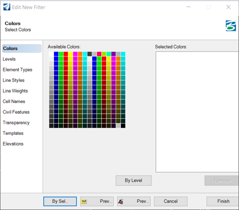
Opens the Edit Filter dialog, wherein you set the parameters for the filter, i.e., levels, colors, civil features, etcetera. Set the parameters by clicking the category to the left, then selecting the parameters. Define a selection set, select the category, then click By Sel. The software autopopulates the fields, based on the elements in the selection set. Multiple selections are supported (Choose six colors or five levels, etcetera.) To view how many elements match the filter, click Preview. All elements in the view that fit the filter are highlighted. Once setting the parameters is complete, click Finish to close the editor and return to the Filter Manager dialog. |
Filter By
The Filter By section displays at a glance which categories are being specified in the current filter. For example, if you used level and color to define the filter, the level and color items are toggled on, once the filter is finished.
Refer to the MicroStation help topic for more information on levels, color, line weight, line style, and other element attributes.
Refer to the MicroStation Other Element Attributes help topic for more information on Transparency.
Refer to the MicroStation Other Element Attributes help topic for more information on Element Template.
For Cell Names, highlight the cell and click Add -> to add to the list. Multiple cells can be selected at one time. To remove, highlight the cell in the left list and click <- Remove. All or None options are supported to add or remove entire lists.
For Civil Features, highlight the civil feature and click Add -> to add to the list. Multiple features can be selected at one time. To remove, highlight the feature in the left list and click <- Remove. All or None options are supported to add or remove entire lists.
The Elevations option is useful to remove data outside the range of interest. For example, data may have 0 elevation data that would skew the terrain model. Specific values (such as 0) can be excluded or an elevation range can be excluded. Note this is exclusion, not inclusion.
Create a Filter Group
Once you have created a minimum of one filter, you can create a filter group. The general workflow is:
-
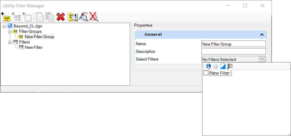
Highlight Utility Filter Groups, right-click and select New Utility Filter group. A line is added to the hierarchy which can be renamed at any time. You can also add an optional description. Keep in mind the Name is what is displayed in the Create Terrain by Filter Group tool.
-
Click Filters to open the Select Filter dialog. The left pane displays all filters currently defined.
-
Highlight the filters to include in the group (in the left pane) and click Add. The filters are moved to the right pane. If you add one by mistake, highlight the filter in the right pane, and click Remove.
-
When the desired filters are selected, click OK to close the dialog and create the filter group. Note a filter can belong to numerous filter groups.
Utility Manager Toolbar
Several tools are located at the top of the dialog for easy access:
|
Settings |
Description |
|
Creates an empty filter group. |
|
|
Creates an empty filter. |
|
|
Select a design file element from active or reference file and this command uses the symbology to fill in the attributes in the filter. |
|
|
Adds filter or group to clip board for paste command. |
|
|
Adds entry from clipboard to list, if the name exists a numeral 1 or greater is added, enter new name or rename later. |
|
|
Deletes the entry. |
|
|
Places all the elements that pass the filter into highlight. |
|
|
Removes all the highlight from elements previewed. |


Properties
The mode for properties changes according to the active selection in the tree view to provide the top level properties for Filters or Filter Groups.
Common properties
Name - User definable description must be unique in current DGN.
Description - User definable description.
Filter Group Properties
Add or Remove Filters - allows selection of available filters.
Filter Properties
Name - the name of the filter.
Description - optional field that can be used to describe the filter.
Type - select either Conduit or Node.
Vertical Offset - a vertical offset measured from the selected elevation source.
Elevation Source - select either Surface or Element.
(For a Node Filter only) Bottom Source - select either Found Point or Conduit Elevation
(For a Node Filter only) Depth - the depth for the node. Used if the Bottom Source is not found
Search Radius - for a Node filter, this is a plan distance from the found top point, which is used to search for the bottom point. For a Conduit filter, if the end points of the graphics being extracted for the conduits are within this value, then a single node is created, instead of multiple nodes.
Edit Filter / Edit Top Filter / Edit Bottom Filter - opens the Edit Filter dialogue.
Feature Definition - select from the available feature definitions for nodes.
Filter By - allows high level selection of properties defined in the Filter to be used.
Edit Filter
The form lists Element Selection modes in the left hand view, available property information and the Selected Types. When adding by Selection all properties are loaded as active making the Filter very selective and specific for that selection. Multiple selections can be made in any filter.
Example
The Level - Water Pipes may contain multiple features that use different Linetypes for different diameter pipes. Alternatively, different diameter water pipes may be drawn on different levels. Either way, you will normally want to set up specific filters, based on unique properties, so that each filter can be mapped to a specific diameter in the selected feature definition.
For nodes, both the top and bottom filters will normally be set up so that each one searches for a specific cell. Each filter will have the Element Type set to Cell, and the Cell Name set to the cell used to draw the graphic. If the bottom of the node has been surveyed and drawn in the graphics, this means that the filter can find it, and the depth of the resulting node will be correct.
Filters for both nodes and conduits need to have the relevant Element Types specified.
