Inlet Catalog Dialog Box
The Inlet Catalog dialog box allows you to create, edit, and delete inlet definitions that can then be assigned to catchment elements in your model.
The following inlet types are available from this dialog:
- Combination
- Curb
- Ditch
- Grate
- Slot
- Flow to Inlet vs. Flow Captured
- Gutter Depth vs. Captured Flow
- Kerb (United kingdom)
- Grating (United Kingdom)
You can also import an inlet definition from the Inlet Libraries Engineering Library, and export inlet definitions to the Engineering Library for later use.
The dialog box contains a list pane on the left and a tabbed input data area on the right, and includes the following controls:
New: Creates a new inlet definition in the list pane on the left.
Duplicate: Copies the currently highlighted inlet definition.
Delete: Deletes the currently highlighted inlet definition.
Rename: Lets you rename the currently highlighted inlet definition.
![]()
Report: Lets you generate a preformatted report that
contains the input data associated with the currently highlighted inlet
definition.

Synchronization Options: Clicking this button opens a submenu containing the following commands:
- Browse Engineering Library--Opens the Engineering Library manager dialog, allowing you to browse the Inlet Libraries.
- Synchronize From Library--Lets you update a set of inlet definitions previously imported from one of the Inlet Libraries. The updates reflect changes that have been made to the library since it was imported.
- Synchronize To Library--Lets you update one of the existing Inlet Libraries using current inlet definitions that were initially imported but have since been modified.
- Import From Library--Lets you import a inlet definition from one of the existing Inlet Libraries.
- Export To Library--Lets you export the current inlet definitions to one of the existing Inlet Libraries.
- Connect to Library--Lets you create a connection between the inlet catalog and the specified engineering library.
The fields and controls that appear in the tabbed area depend on which inlet type is chosen. Not all fields will be available for all inlet types.
Inlet Tab
- Structure Width: Define the width of the inlet structure. This field is available for all inlet types.
- Structure Length: Define the length of the inlet structure. This field is available for all inlet types.
- Curb Opening Height: Define the height of the curb opening. This field is available for Curb and Combination inlet types.
- Default Curb Opening Length: Define the default length of the curb opening. This field is available for Curb and Combination inlet types.
- Local Depression: Define the depth of the gutter depression at the inlet, if any. This field is available for Curb and Combination inlet types.
- Depression Width: Define the width of the gutter depression at the inlet, if any. This field is available for Curb and Combination inlet types.
- Throat Type: Choose the throat type. The throat type defines the shape of curb opening. This field is available for Curb and Combination inlet types.
- Throat Angle: Define the angle of the inlet throat. This field is only available when the Inclined Throat Type is chosen. This field is available for Curb and Combination inlet types.
- Grate Type: Choose the grating type. This field is available for Combination, Ditch, and Grating inlet types.
- Grate Width: Define the width of the grating. This field is available for Combination, Ditch, and Grating inlet types.
- Default Grate Length: Define the default length of the grating. This field is available for Combination, Ditch, and Grating inlet types.
- Slot Width: Define the default width of the slot. This field is available for Slot inlet type.
- Default Slot Length: Define the default length of the slot. This field is available for Slot inlet type.
- Flow to Inlet vs. Flow Captured Table: This table is only available when the Flow to Inlet vs. Flow Captured Inlet type is selected. It allows you to define the amount of Flow Captured at various Flow to Inlet points. Click the New button to add a new row to the table. Click the Delete button to remove the currently highlighted row from the table.
- Gutter Depth vs. Captured Flow Table: This table is only available when the Gutter Depth vs. Captured Flow Inlet type is selected. It allows you to define the amount of Captured Flow at various Gutter Depth values. Click the New button to add a new row to the table. Click the Delete button to remove the currently highlighted row from the table.
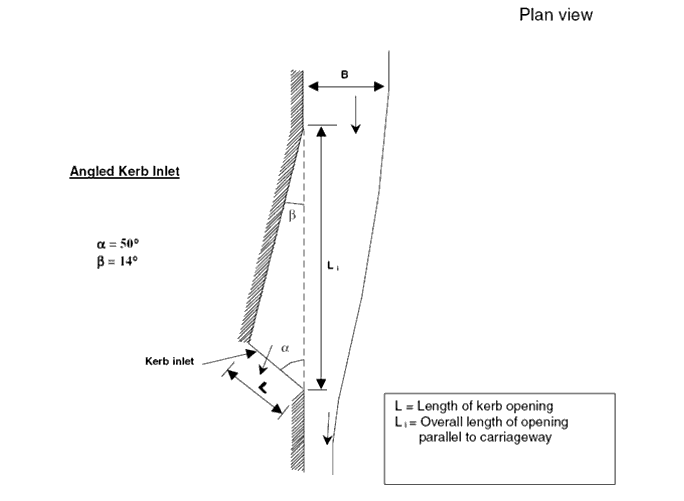
- Kerb Angle (Alpha): The angle of alpha as in the diagram below.
- Kerb Angle (Beta): The angle of beta as in the diagram below.
Design Tab
This tab contains a list of allowable design lengths. When performing a design analysis, the program will only be able to select inlets of one of lengths specified here. To add a new length to the list click the New button and type in the length. To remove a length from the list, highlight it and click the Delete button.
Notes Tab
This tab contains a text field that allows you to enter descriptive notes that will be associated with the currently highlighted inlet definition.
Library Tab
This tab displays information about the inlet definition that is currently highlighted in the list pane. If the inlet definition is derived from an engineering library, the synchronization details can be found here. If the inlet definition was created manually for this model, the synchronization details will display the message Orphan (local), indicating that the inlet definition was not derived from a library entry.
- Click the New button above the list pane.
- Type a name for the inlet.
- Choose an Inlet Type from the Inlet Type field in the tabbed section to the right.
- Type in input data in the input fields in the tabbed section to the right. The available fields will vary according to the Inlet Type that is chosen.
- Click Close when you have finished defining the inlet parameters.
To import an inlet from the Engineering Library:
- Click the Synchronization Options button and select Import From Library from the submenu.
- Expand the Inlet Libraries node to view all of the existing Inlet Libraries. There will be the default Inlets Library, along with any additional custom libraries you've created.
- Expand the desired library to view all of the inlet definitions within that library. Click on the inlet definitions to view their properties on the right side of the dialog.
- When you have chosen the desired inlet definition click the Select button. The new inlet will appear in the list pane.
Default Curb and Grate Lengths
When you assign a catalog inlet to a catch basin, Drainage and Utilities will assign the default curb and grate length values for that catalog inlet (as defined in the Default Curb Opening Length and Default Grate Length fields) to the catch basin’s curb opening length and grate length respectively. However, you can also manually change the values for the catch basin so that it the catalog inlet values and catch basin values are not in sync. When you perform an analysis computation run, the value in the catch basin attribute is used. When you do a design run, the value of the catch basin attribute is initially used, but then that catch basin attribute can be changed during design to one of the available curb opening lengths listed in the design tab of the referenced catalog inlet.