Orthophoto/DSM
Produce interoperable raster layers for visualization and analysis in third-party GIS/CAD software or image processing tools.
Note: When using tiling, orthophoto/DSM productions generate one file per tile. You can use the command Merge orthophoto parts (available once ContextCapture production is complete) to create a single merged file for the orthophoto and for the DSM.
Options
- Sampling distance: sampling distance option. Unit depends on the selected Spatial reference system.
- Maximum image part dimension (px): define the maximum tile size for the resulting raster file.
- Projection mode: define how the 2D data layer is processed from the 3D model (Highest point or Lowest point).
- Orthophoto/DSM: enable or disable the corresponding production.
- Color source:
Optimized computation (visible colors): the best photos with visible colors band are selected according to the actual projection.
Optimized computation (thermal): the best photos with thermal band are selected according to the actual projection.
Reference 3D model visible color: keep the internal reference 3D model with visible colors as is (mush faster).
Reference 3D model (thermal): keep the internal reference 3D model with thermal band as is (mush faster).
- No data: pixel value or color representing no information.
 The reference 3D model texture
and geometry must be available to process orthophoto.
The reference 3D model texture
and geometry must be available to process orthophoto.
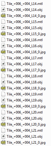
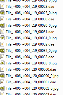
About LOD naming convention
3D mesh productions with LOD use a specific naming convention for node files according to tile name, level of detail resolution, and node path (for LOD trees).
For a node file "Tile_+000_+003_L20_000013.dae", the meaning is the following:
Each digit of the node path corresponds to a child index (zero-based) in the tree. For quadtree and octree productions, the child index unambiguously indicates the quadrant/octant of the child node.