Diagram
Use the Diagram tool, or its respective icon, to display the results in a graphical format as shown in Figure below.
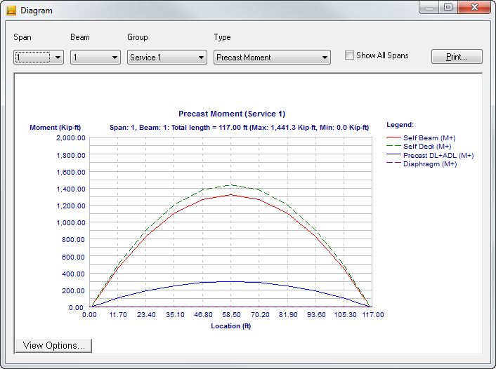
Use the lists at the top of the screen to select specific information to view. After the analysis has been performed, Moment and Shear diagrams are available for all beams. Half beam results only are displayed for stresses at release, positive stresses, and negative stresses. Also note the shear diagram plots the absolute shear values.
Select the Show All Spans check box to view the graphics by span or for all spans defined. Any of the diagrams displayed on this screen can be printed individually by clicking Print.
Graphics Windows
This screen includes a graphic window that displays a representation of the item you are constructing. Making changes to the graphics can only be accomplished by changing the field values in the data file.
| Copy View |
This command copies the current contents of the graphics window to the Clipboard. You can then paste it as a graphic image into another application such as Microsoft® Word®. The image will be copied as a Windows Enhanced Metafile, usually at the size you see on the screen. Once you paste the image, it can usually be resized as needed. |
| Print View |
This command opens the Print Setup dialog box, which allows you to print the current contents of the graphic window to any supported printer. |
| Export/Save View |
This command allows
you to export/save the contents of a graphic window to another file format.
Precast/Prestressed Girder
currently supports three file formats for export/save: Windows Enhanced
Metafiles (.emf.), AutoCAD Data Exchange Format (.dxf), and Bentley
Microstation design files (.dgn). Prior to export/save, you must specify the
file name, format, and location of the file using the Export/Save dialog box.
|
| Full Screen Viewer |
This command opens the selected graphic in a new, independent window that offers advanced zoom and pan functionality. |