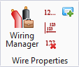
Wiring Manager
 Used to edit wire tags and wire
properties, as well as add labels to wires, and also modify and force
connections.
Used to edit wire tags and wire
properties, as well as add labels to wires, and also modify and force
connections.
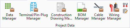
Accessed from:
Some key terminology in the Wiring Manager includes:
- Wire: In schematic mode this refers to the lines we draw that represent wires. The term "logical line" is a more generic term.
- Wire Tag: A value (wire number) assigned to a wire to identify it.
- Wire Number: The combination of installation, location, and wire tag.
- Wire Property: A piece of information that helps describe the wire. Examples are gauge, color, voltage, etc.
- Wire Label: In schematic mode, this refers to the text that we place near the wire so that the user can visually identify the wire.
| Setting | Description |
|---|---|
| Add Device | Adds a device or terminal that does not exist in the schematic into the potential. |
| Delete | Deletes an added device. |
| Star Connection Point | If a connection point is a child of another
connection point, it can either connect to the previous child or to the parent.
A star connection point connects to its parent. A non-star connection point
connects to the previous child. The first child has no previous child,
therefore it must be a star.
Note: When
dragging-and-dropping connection points in the tree, the default is to place
them above or below the target node you are dropping on. This will be indicated
by a blue arrow pointing up or down. Hover over the node and the blue arrow
will turn yellow, allowing you to drop the connection point as a child node (or
hold down the
<Shift> key while dragging).
|
| Single Wire Connection Point | Designates that the connection point may be connected to only one other connection point. This requires the connection point to be at the top or bottom of the tree, or the top or bottom of any child list. You can only move these connection point types to a position in the tree where it will continue to be connected to only one other device. If the part number of the device designates that the connection point accepts a single wire connection, you will not be able to turn off that designation. |
| Move Up | Moves the connection point up one place. |
| Move Down | Moves the connection point down one place. |
| Search | This field enables you to search for a text string in the connection points. |
| Force Connection | Forces the connection of two connection points. The software will not attempt to reorder them if it finds a better connection opportunity. |
| Unforce Connection | Unforces a connection. |
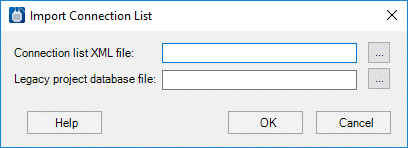
| Import Legacy Connection List | Displays the
Import Connection List dialog, which
enables you to import forced connections from legacy versions of
Bentley Substation
.
Use the Browse button next to the Connection List XML File field to locate an external connection list file (.xml). Use the Browse button next to the Legacy Project Database File field to locate a legacy Bentley Substation project file (.mdb). Press OK to import the forced connections. |
| Wire Options | Changes the Project Options without closing the dialog. Options are provided to change Label Preferences, Wire Layer Configuration, and Default Wire Properties. |
| Reset Layout | The panels in the Wiring Manager can be rearranged. This will reset the layout to the original look. This is especially useful if you close a panel you need. |
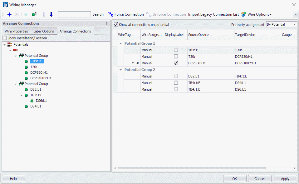
| Show all connections on potential | If you were to right-click on a segment of a circuit with multiple wire branches on the same potential, with this option enabled, all of the from-to connections on that potential would be displayed in the Wiring Manager. Otherwise, you can have it display only the from-to connections the selected segment represents. |
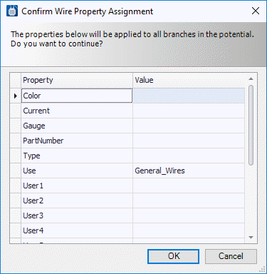
| Property assignment | By default, property assignment for a potential will be By Potential. This means that each branch in the potential will have the same properties (i.e. gauge, color, etc.). You can change this setting to By Branch and then each branch can have different property values. If you change from By Branch to By Potential, a dialog will appear asking you to confirm the properties to be assigned to all branches. |
| Display Label | This check box will be checked for the branch assigned to the wire segment. The check-box will also be checked for any branch that already has a label. If you check this box, a label will be automatically added to a wire segment the branch is assigned to. |
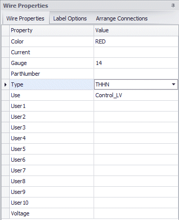
| Wire Properties Tab | Displays the detailed properties assigned to the row(s) selected in the main connection grid. Properties that differ between the selection connection grid rows will be designed as <Varies>. You can edit any of the wire properties in this tab. |
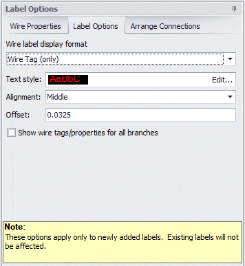
| Label Options Tab | Enables you to adjust the settings that control how labels should be displayed. Changes made in this tab only affect labels that will be added. Any existing labels will be unaffected. |
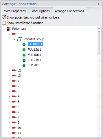
| Arrange Connections Tab | Displays the connection points in the potential in a
tree view. You can drag-and-drop connection points in the tree view in order to
rearrange the connection order. In order to maintain the integrity of the
connection list, once you start moving connection points in a potential, the
software automatically forces the connections.
Note: You may
unforce connections; however, this may cause the software to rearrange some of
the connection points the next time it compiles the connections. After
unforcing connections, wire properties will temporarily be marked as Read Only
until you click
Apply or
OK so that the software can commit the
forced routing changes and recompile the connection list.
|