| Catalog Tree
|
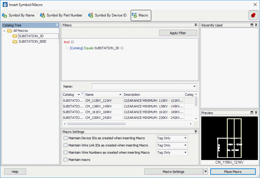
Enables you to navigate to a specific macro location.
You can filter the list of macros by selecting a folder in the tree.
|
| Filters Panel
|
-
Advanced Filter Editor - Using this
control you can create any number of conditions and combine them in any manner
using any logical operator. Click the + button to add a new condition. Select
the field you want to filter on. Then pick the logical operator and specify
your criteria. You can click the
X to clear a filter condition.
-
Apply Filter - Press this button to
apply the filter settings.
|
| Name
|
If you know the name of the macro that you wish to
place in the drawing, you can enter it in this field. As you enter the name of
the macro, any existing symbols that match the entered characters will be
listed in the grid.
|
| Symbol List
|
The software lists all the macros that match any
filters that you have applied. You can apply additional filters by selecting a
field heading and picking the down arrow which displays all the values for that
field. Picking a value will filter the list of macros and only list those that
have that value.
Clicking on a field heading will sort the list in
ascending order. Clicking a second time will sort it in descending order.
You can click and drag the fields in any order you
wish. Right clicking on any field heading will allow you select which fields
from the database you wish to display. You can toggle on/off fields as desired.
You can select the macro that you want to place from
the list.
|
| Macro Settings
|
- If you do not want
the device IDs of any symbols in the macro to be automatically updated to
reflect their new position, select the
Maintain Device IDs as created when inserting
Macro check-box. (You will still be prompted with the original
device ID). You can choose to maintain the device tag only or the complete ID.
- If wire links were
stored as part of the macro and the
Maintain Wire Link IDs as created when inserting
Macro check-box is selected, these will appear when the macro is
placed and will not be updated automatically to reflect their new position. You
can choose to maintain the device tag only or the complete ID.
- If wire numbers were
stored as part of the macro and the
Maintain Wire Numbers as created when inserting
Macro check-box is selected, these will appear when the macro is
placed. If the macro's wire numbers are connected to existing wire numbers in
the project, the existing wire numbers will take precedence. If the wire
numbers would create a duplicate wire number, they will have ? appended. You
can choose to maintain the wire tag only or the complete ID.
- When inserting a
macro, the
Maintain macro check-box enables you to
control whether the macro elements will maintain their associativity.
|
| Recently Used Panel
|
Lists the last 10 macros that you had previously
placed. The list is remembered the next time you restart the software and is
not project specific.
|
| Preview Panel
|
Shows a preview of the macro for the selected part
number based on the current drawing mode.
|
| Settings Flyout
|
Selecting the down arrow on this button will flyout
the button menu with three choices:
-
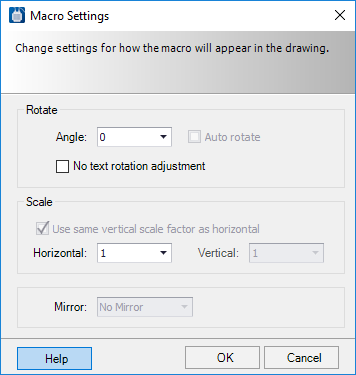
Macro Settings - Opens the
Macro Settings dialog which allows
you to specify a
rotation angle, scale factor, and
mirror setting which gets applied to
any new symbol you insert.
-
Group Settings - Opens the group
settings dialog. If you select more than one item you can place them as a
group. You can make settings to determine how symbols are placed as a group.
-
Reset Dialog - If you had changed the layout of the dialog from the
default or closed any panels you can reset the dialog to its default layout.
|
| Place Macro
|
Places a new macro, based on the symbol settings
specified.
|
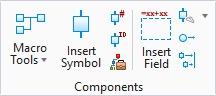
 Used to place objects in the
current model using a Macro. A macro is a collection of symbols, wires and
other elements that can be placed on a drawing. A number of macros are provided
with the software or the user can also create custom macros.
Used to place objects in the
current model using a Macro. A macro is a collection of symbols, wires and
other elements that can be placed on a drawing. A number of macros are provided
with the software or the user can also create custom macros.