Insert Balloon
 Places a numbered balloon beside
a symbol in a drawing that indicates the position of that component in the Bill
of Materials list.
Places a numbered balloon beside
a symbol in a drawing that indicates the position of that component in the Bill
of Materials list.
Accessed from:
Balloons can be placed in any type of drawing, not just panel layouts. You can make settings for balloon appearance in the Project Options Balloon Settings dialog.

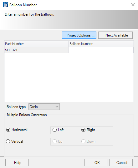
The Balloon Number dialog enables you to enter a balloon number for a selected symbol.
| Setting | Description | ||||
|---|---|---|---|---|---|
| Project Options | Displays the Balloon Settings dialog, which enables you to make settings that determine how balloons appear in various drawing types. | ||||
| Next Available | Automatically assigns the next available balloon number. | ||||
| Part Number | Displays the accessory kit part numbers as well as the kit parts themselves. | ||||
| Balloon Number | Enter the desired balloon number. | ||||
| Balloon Type | Select the type of balloon to insert from the drop down. | ||||
| Multiple Balloon Orientation | In the Project Options Balloon Settings, if you have
the
Display Separate Balloons For Quantified
Parts check box selected, multiple balloons will be placed for symbols
that have multiple part numbers assigned. When you select such a symbol when
placing a balloon the
Horizontal and
Vertical settings indicate the preferred
orientation of the balloon text. Refer to the images below on how the different
orientations are displayed:
|


The software will prompt you to Pick leader start or balloon insert point. Click on the point where you wish the head of the arrow from the balloon to appear. The software will prompt To point...? Click where you wish the other end of the leader from the balloon to end. You can click on multiple points to create segments in the leader. If you wish the balloon to appear with no leader, simply press <Enter> , do not define any additional points.

Place Balloons on Multiple Symbols
When launching the Insert Balloon command, you can select multiple symbols to balloon. When more than one symbol is selected, the Select a Symbol to Balloon dialog displays. This allows you to select which of the selected symbols to balloon. The window selection option makes it easy when there are multiple symbols in close proximity and they are hard to visually separate. Select them all and then pick which one to balloon from the list.

The selected symbol will appear highlighted in the drawing. Click OK to proceed with drawing the balloon leader and entering the balloon number. Enter links to how to topics.