Gutter Section Viewer Dialog
If a Gutter link has been set to use gutter sections, from point interrogated from the Terrain Model, the cross section points can be reviewed from the Gutter Section Viewer dialog. To navigate to this dialog, set the gutter link’s attribute of Gutter Type to Use Gutter Sections. Then select […] for the collection attributed titled Gutter Sections.
Sections List Buttons


Sections List
Displays the list stations for each of the sections associated with the gutter. Click the section to view the section and its properties.
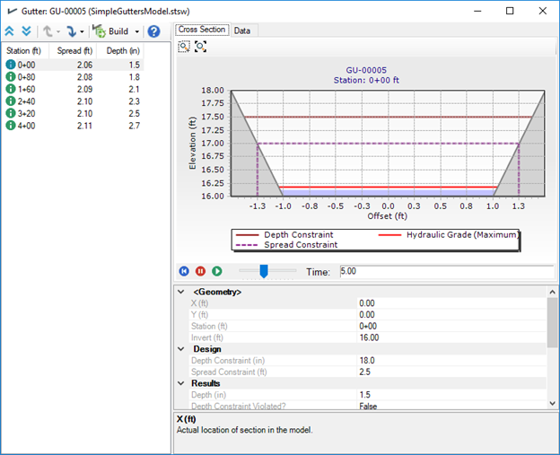
Sections Viewer Graph Tab
Displays a graph view of the gutter section that is currently highlighted in the Sections List.
If results exist, the graph will display the following lines:

The time browser will update the HGL value in the cross section viewer and time-variable property grid results
Section Viewer Data Tab
Displays the data values of the gutter section that is currently highlighted in the Sections List.
Section Properties
- Station - Location of section measured from the start node of the gutter.
- X - Actual location of section in the model.
- Y - Actual location of section in the model.
- Invert - Bottom elevation of the gutter section.
- Angle - Gutter cross section angle to road is the angle of the cross-section line to the X coordinate line.
- Depth Constraint - The depth design constraint that is used during the analysis.
- Spread Constraint - The spread design constraint that is used during the analysis.
- Depth - Depth of flow in gutter section at current time step.
- Depth Constraint Violated? - Is True if the depth constraint is violated at the currently selected time.
- Flow - Flow in gutter section at current time step.
- Spread - Top width of flow in gutter section at current time step.
- Spread Constraint Violated? - Is True if the spread constraint is violated at the currently selected time.
- Velocity - Velocity of flow in gutter section at current time step.
- Depth (Maximum) - The maximum flow depth that occurs at the gutter section.
- Depth Constraint Ever Violated? - Is True if the depth design constraint is violated at any point during the simulation.
- Spread (Maximum) - The maximum spread that occurs at the gutter section.
- Spread Constraint Ever Violated? - Is True if the spread design constraint is violated at any point during the simulation.
SWMM - Variable Gutter Sections
- First the SWMM engine calculates and figures out the carryover flow entering the gutter and the total flow leaving gutter.
- After the SWMM engine completes, the depth and spreads are computed at each of the sections based on linearly interpolating the bounding flows based on the station of the section.
Dynamic Wave - Variable Cross Sections
When using Gutter Sections derived from the terrain model the DW engine works as follows:
- First the DW engine calculates and figures out the carryover flow entering the gutter and the total flow leaving gutter.
- After the DW engine completes, the flow for a gutter section is derived by linearly interpolating the bounding flows: flow at the individual section: (start flow) + station * (stop flow - start flow)/(pipe length)
- With the interpolated flow at a particular gutter section, the depth and spread at the section are computed as if it was an irregular channel like FlowMaster: assuming Manning’s Uniform Flow.
- Statistics of Max Depth and Max Spread are computed for each section, and compare to the design threshold values for depth and spread for each gutter.
Build Gutter Sections Options
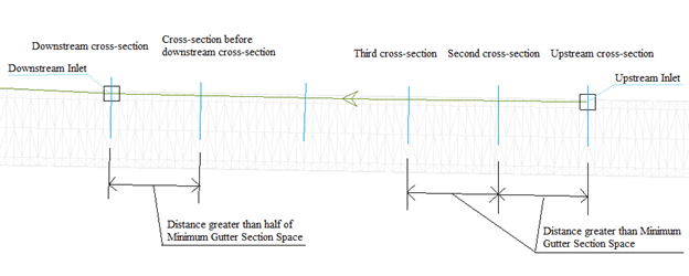
- Minimum Spacing Between
Sections: Only when distance between 2 gutter cross-sections is larger than
this value will a gutter section be added. Sections at the upstream inlet and
downstream inlet are always added. Other middle sections are added between the
upstream inlet section and downstream inlet section. Space between 2 sections
should be larger than the Minimum Gutter Section Space value, except the last
two sections (the section before downstream inlet section and downstream inlet
section). The Space between the last 2 sections can be smaller than the Minimum
Gutter Section Space value but must be larger than half of the Minimum Gutter
Section Space value.
The following is an example of gutter cross-sections between upstream and downstream inlets, in which blue lines are gutter cross-sections to be derived from terrain model.
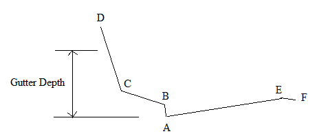
- Maximum Bank Search Height: For a composite terrain model with road design and natural area, the left or right bank of the gutter may be much higher than the gutter invert and many more points can be added to the gutter station-elevation curve. For left bank and right bank of a gutter, we only find one point with depth more than Gutter Depth (or Maximum Bank Search Height) value. In the following example, when we find point D, we stop the search on the left bank of the gutter cross-section.
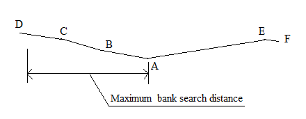
- Maximum Bank Search Distance: For a natural terrain model, if the bank slope is small, the bank horizontal length can be very large. Maximum bank search distance is used to avoid having very long gutter banks. In searching gutter left bank or right bank, when the distance between the searched point and the point with lowest elevation in the cross-section is greater than the specified Maximum bank search distance, the search for the bank will stop. In the following example, when the horizontal distance between the searched point D and the lowest point A in cross-section is larger than Maximum Bank Search Distance, the search for the bank will stop.
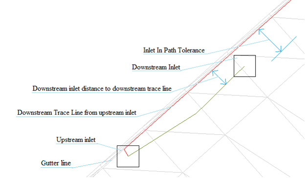
- Maximum Inlet Offset Search Distance: To create a valid gutter link between 2 inlets, the downstream inlet must be in the downstream trace path from the upstream inlet. Since the inlet may not be exactly laid out in the gutter, a Maximum Inlet Offset Search Distance (or Inlet In Path Tolerance) is used to check if the downstream inlet is in the downstream path from an upstream inlet. If the distance from the center of the downstream inlet to the downstream trace line from upstream inlet is less than the Maximum Inlet Offset Search Distance value, the downstream inlet is assumed to be at the downstream trace path from the upstream inlet. The following is an example of a downstream inlet in the downstream trace path from an upstream inlet, where distance from downstream inlet to the downstream trace path is smaller than the Maximum Inlet Offset Search Distance value.
Methodology
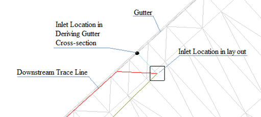
To Find the Inlet Locations in a Gutter: Since the inlets may not be exactly laid out in gutters, the software needs to find the inlet locations in the gutter and search gutter cross-sections from the inlet location in the gutter. A perpendicular line is drawn from inlet to gutter line and the intersecting point is the inlet location in gutter. The following is an example of finding the inlet location in gutter:
To Find the Gutter Cross-Section:
From a point in a gutter, draw a line perpendicular to the gutter line, which is the downstream trace line. From the point in either direction of the line, search point in increasing elevation order until invalid point or a point with lower elevation than last searched point is searched. Pass the searched 2 points in both directions to the terrain model to get the profile information between the two points. Remove the duplicated points and the points that are beyond the gutter bank to get the gutter cross-section points. With Gutter Depth value used, when a point with depth larger than the Gutter Depth value, the search in that direction is stopped to avoid getting too many points in the gutter cross-section.
In the following gutter profiling example, search gutter cross-section points from lowest elevation point A in gutter to both sides. When It reaches point D (which has higher elevation than elevation at A plus Gutter Depth), the search will stop on that side and point D is added to gutter cross-section. When search reaches point F which has lower elevation than last searched point E, the search will stop on that side and point F is not added to gutter cross-section.
