To Define and Place Multiple Connection Points on Equipment
-
Click
Parametric Content Creation in the
Project Setup group on the
Manage ribbon.
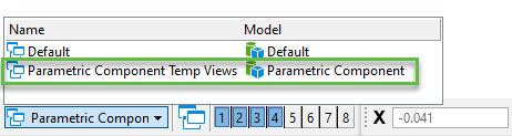
It opens the temporary model view named Parametric Component Temp Views and also opens the Parameterized Modeling dialog.
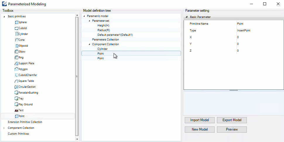
- Select the element from the Basic primitives list, for example, Cylinder and drag-drop the element under the Component Collection of Model definition tree.
- Select the Point element and change its Type to ConnectionPoint from the drop-down list.
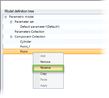
- (Optional) Select the Point element and right mouse-click to rename the element by selecting Rename option.
- (Optional)
Click
Preview.
You can see connection points in the View, Parametric Component of DGN file.
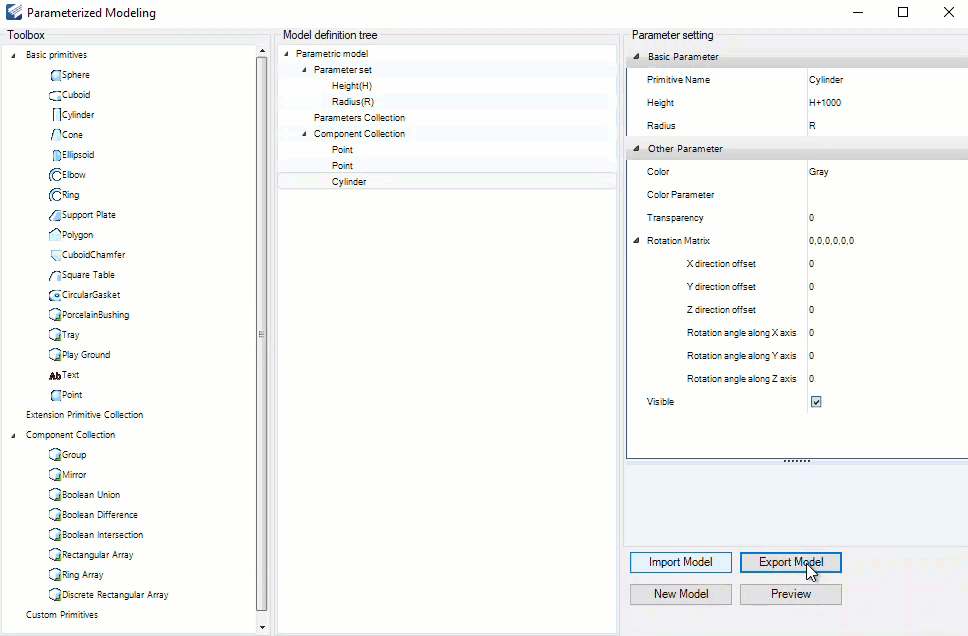
- Click Export Model.
-
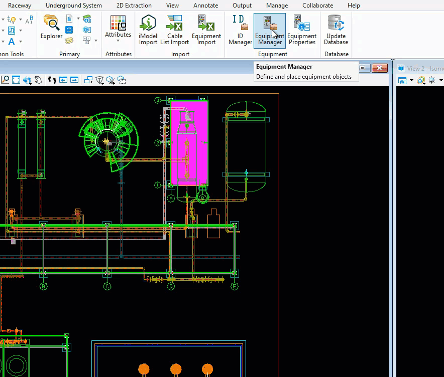
Click
Equipment Manager from the
Equipment group under the
Equipment & Cable Tab.
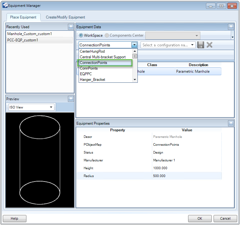
The Equipment Manager dialog opens.
-
Select the
New option in the
Create/Modify Equipment Tab.
- Select the ParametricObject from template option.
-
Select the
POB_Parametric_Multi-CP_Template template
from the
ParametricObject from
template dialog and click
Open.
It loads the template with its properties in the Equipment Manager dialog.
- Enter the PObjectMap filename similar to *.pmd filename created in Step 6 in the Equipment Properties section and click OK.
-
Click
Yes in the
BRCM
Request dialog to save the changes.
The Save As dialog opens.
- Enter the POB XML File (*.xml) filename in the Save As dialog and click Save.
- Open the MAP file ConnectionPoints.map and enter the Path, DNAName, Tag and ClassName similar to *.pmd filename and save the file.
- Open Equipment Manager dialog and select the file from the dropdown list.
- Click OK and place the equipment with multiple connection points in the DGN file.