To Define Connections of Path Nodes
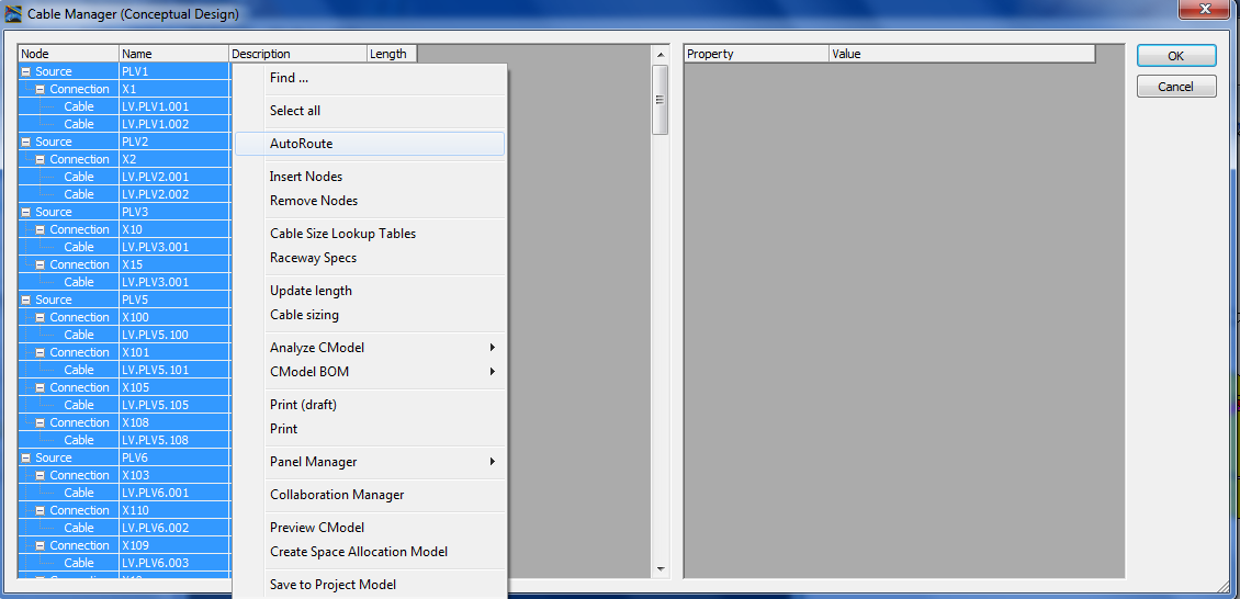
- Start the Cable Manager (Conceptual Design).
- After the reading and assigning cable lists and the node map, press the right mouse button and select AutoConnect.
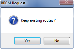
- Press Yes in the following dialog.
- Press the right mouse button and Select All.
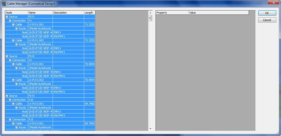
- Press the right mouse button and select Update Length. The lengths are displayed.
- Press the right mouse button and Select All.
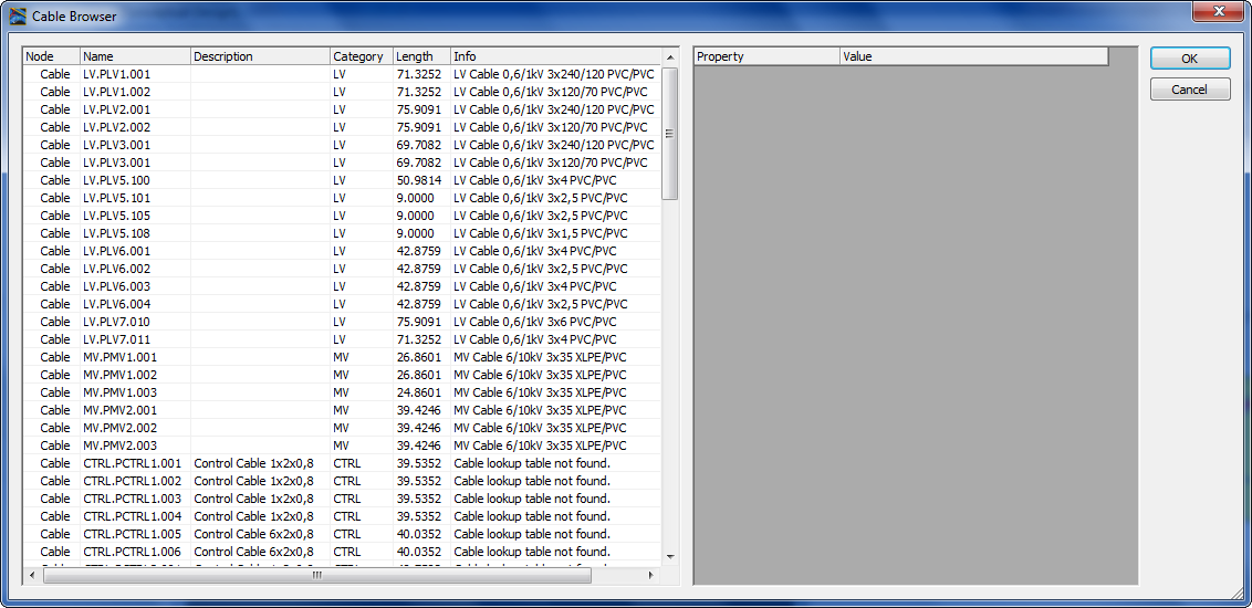
- Press the right mouse button and select Cable Sizing.
- The Cable Browser shows the possible Cable types and sizes. Accept the settings by pressing OK.
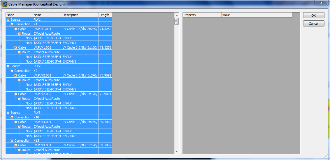
- The cable types and cable sizes are displayed in the Cable Manager.
- Select Preview CModel to see the connections between Source and Target Nodes (shortest distance).
- You can return to the menu with the right mouse button.
- Press Save to Project Model.
- Press the right mouse button and Select All.
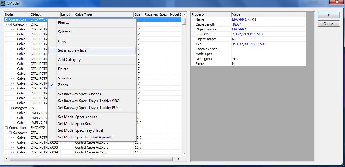
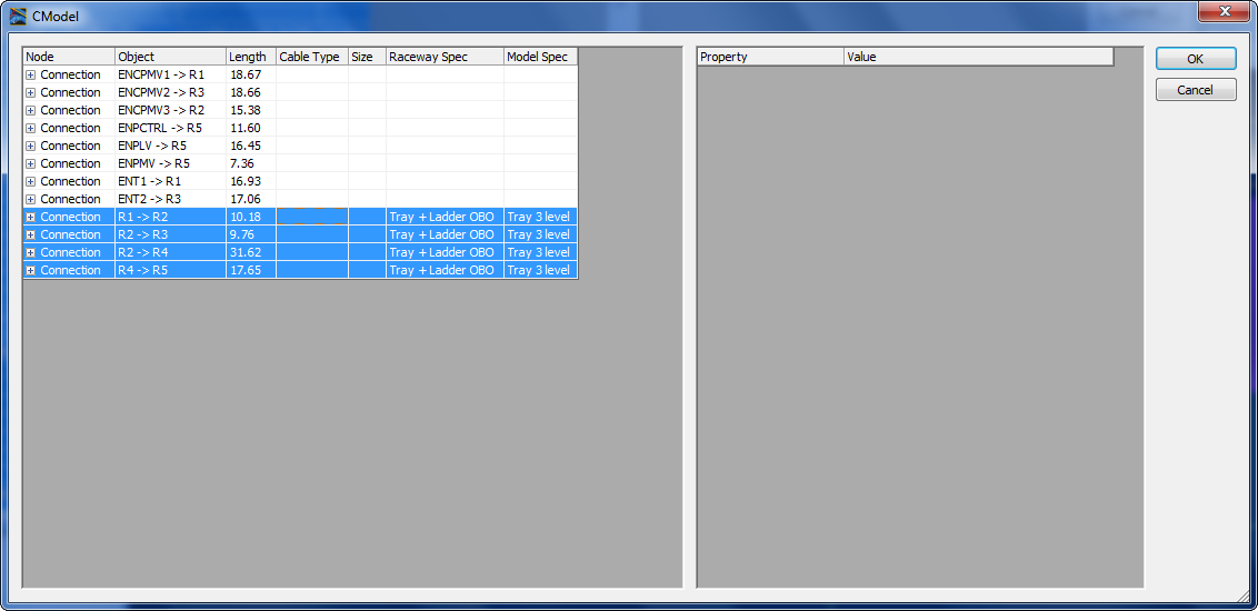
- Press the right mouse button and select Analyze CModel.
- Select the first entry (connection) in list and click select Set max view level.
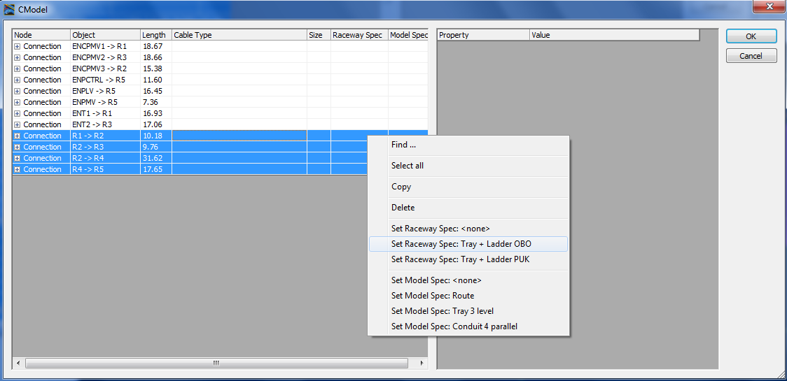
- Select the last four entries (R1->R2, R2->R3, R2->R4, R4-> R5), then use the right mouse button and select Set Raceway Spec: Tray + Ladder OBO.
-
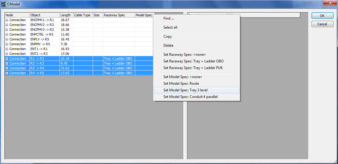
Select the last four entries (R1->R2, R2->R3, R2->R4,
R4-> R5), then use the right mouse button and select
Set Model Spec Tray 3 level.
Result in Cable Manager
- Press OK.
- Press Save to Project Model.
- Press the right mouse button and Select All.
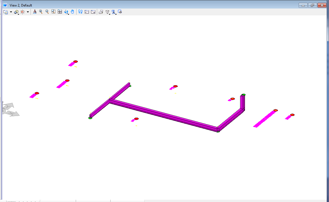
- Press the right mouse button and select Create Space Allocation Model. Result in Design File:
- Use the Update Database function to save the changes to the database.